
Power detection circuit and method of power amplifier

A technology of power detection circuit and power amplifier, which is applied in the directions of amplifiers, improving amplifiers to improve efficiency, and components of amplifying devices, etc., can solve the problems of single compensation function and low flexibility of different amplifiers, so as to meet the needs of compensation and be flexible. High performance and energy saving effect

Pending Publication Date: 2022-05-24
南京锐弘普诚科技有限公司
View PDF0 Cites 0 Cited by
  • Summary
  • Abstract
  • Description
  • Claims
  • Application Information

AI Technical Summary

Problems solved by technology

[0004] The purpose of the present invention is to provide a power detection circuit and method of a power amplifier, aiming to solve the technical problem that the compensation function of the power detection circuit to different amplifiers is relatively single and the flexibility is low in the prior art

Method used


Image

  • Power detection circuit and method of power amplifier
  • Power detection circuit and method of power amplifier

Examples


Embodiment Construction

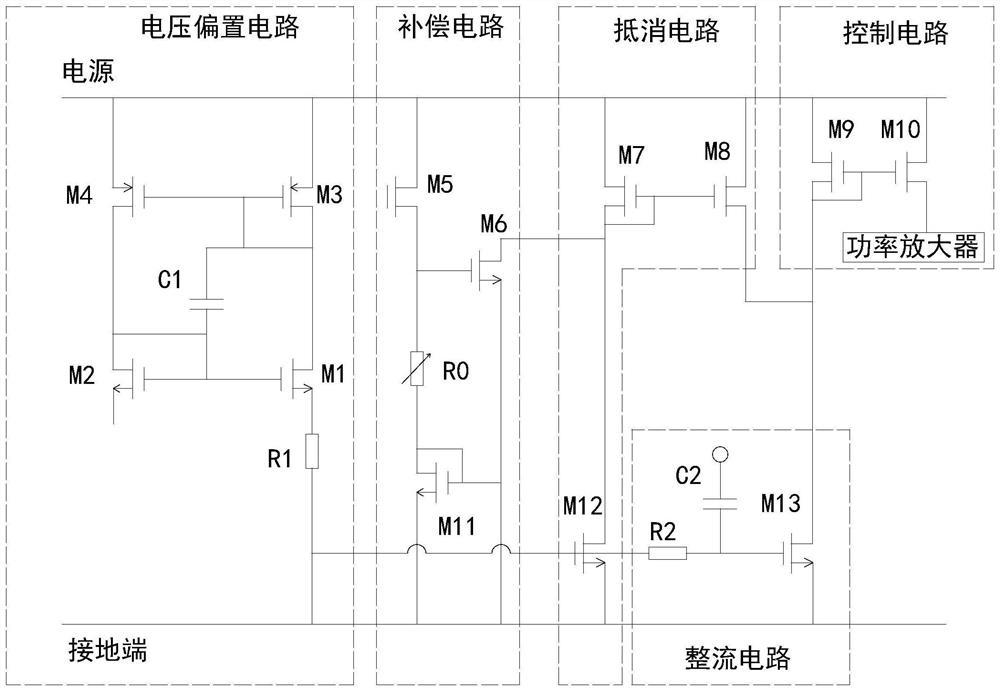
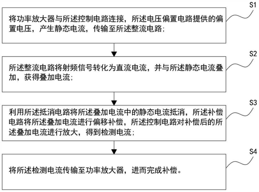
[0020] see figure 1 and figure 2 The present invention provides a power detection circuit of a power amplifier, the power detection circuit of the power amplifier includes a voltage bias circuit, a rectifier circuit, a cancellation circuit, a compensation circuit and a control circuit, and the voltage bias circuit is respectively connected with the rectifier circuit. The circuit is electrically connected to the cancellation circuit, the cancellation circuit is electrically connected to the compensation circuit and the rectification circuit, respectively, and the control circuit is electrically connected to the rectification circuit and the power amplifier, respectively; The setting circuit includes a MOS transistor M1, a MOS transistor M2, a MOS transistor M3, a MOS transistor M4, a bias circuit, a resistor R1 and a capacitor C1. The gate of the MOS transistor M1 is electrically connected to the gate of the MOS transistor M2. The gate of the MOS transistor M3 is electrically...


PUM


Abstract

The invention relates to the technical field of power amplifier detection, in particular to a power detection circuit and method of a power amplifier. When the power supply of the voltage bias circuit is powered on, the capacitor C1 provides conduction voltage drop for the MOS tube in the bias circuit, so that the voltage bias circuit gets rid of a zero-current state, and after the voltage bias circuit is started, the capacitor C1 is in a turn-off state, and at the moment, the starting circuit does not generate power consumption, namely no power consumption is generated, so that electric energy is saved; the direct current offset circuit and the offset compensation circuit are added on the basis of an existing power detection circuit, range adjustment of output current can be achieved, the compensation requirements of different amplifiers can be met, and flexibility is high.

Description

technical field [0001] The invention relates to the technical field of power amplifier detection, in particular to a power detection circuit and method of a power amplifier. Background technique [0002] Modern communication systems use more and more complex modulation methods, which makes the requirements for the linearity performance of RF power amplifiers higher and higher. In order to ensure the efficiency of the PA and improve the linearity performance of the power amplifier is a problem to be solved. [0003] Since the compensation requirements of different amplifiers will change according to the input power, the traditional power detection circuit has a relatively single compensation function for different amplifiers and is less flexible. SUMMARY OF THE INVENTION [0004] The purpose of the present invention is to provide a power detection circuit and method of a power amplifier, which aims to solve the technical problem that the compensation function of the power d...

Claims


Application Information

Patent Timeline
IPC IPC(8): H03F1/02H03F1/32G01R21/00
CPCH03F1/0205H03F1/32G01R21/00Y02D30/70
Inventor 侯杰
Owner 南京锐弘普诚科技有限公司
Learn More