
High-capacity high-reliability rapid switching device

A fast switching, large-capacity technology, applied in circuit devices, emergency power supply arrangements, electrical components, etc., can solve the problems of being easily damaged by external bumps, unable to perform fast switching, and discontinuous machine operation, to avoid shaking and bumping, The effect of avoiding poor contact and avoiding data loss

Inactive Publication Date: 2022-05-24
南京竣望新材料有限公司
View PDF0 Cites 0 Cited by
  • Summary
  • Abstract
  • Description
  • Claims
  • Application Information

AI Technical Summary

Problems solved by technology

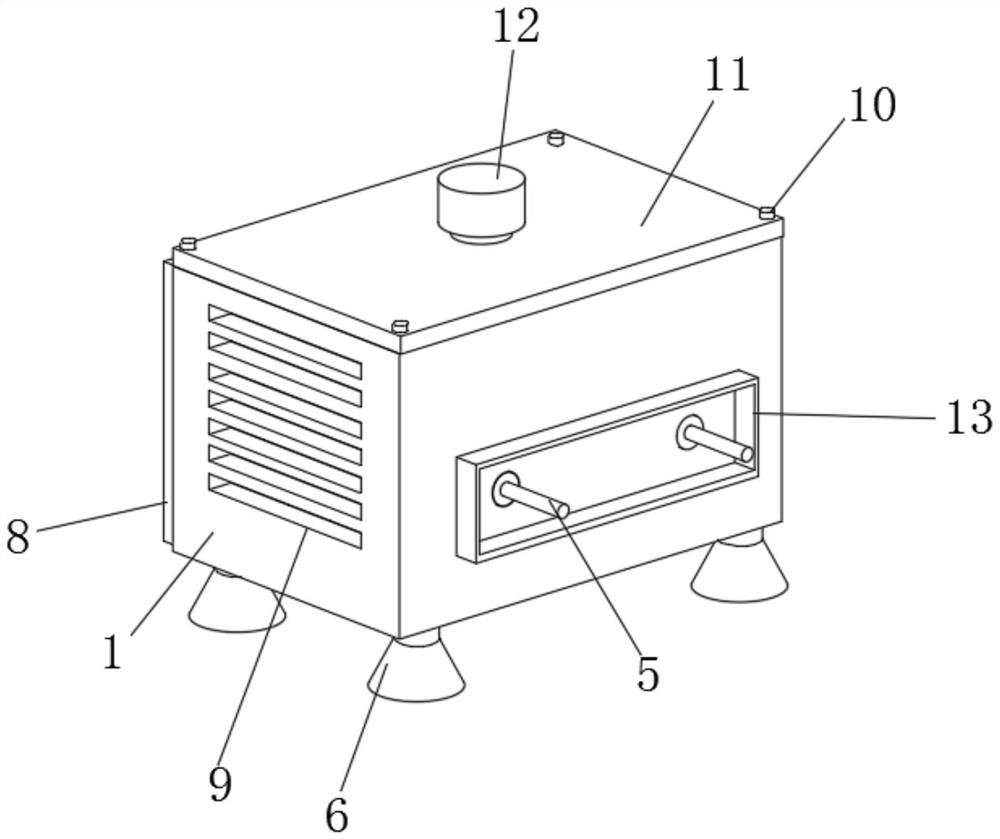
[0002] When the power supply is unexpectedly cut off, the machine will stop running, making the machine run discontinuously. For this reason, a backup power fast switching device that extends the battery life is developed. By installing the backup power that prolongs the battery life and the power supply is switched The fast switching of the device makes it continue to work when the power supply fails, ensuring the continuity of the machine operation. The inventors have found that at least the following problems have not been solved in the prior art: 1. When the existing power supply is switched, there is no It can be switched quickly, otherwise it will easily lead to instant disconnection and data loss; 2. The existing switching device is prone to shaking during the switching process, and the use stability is poor; 3. During the use of the existing switching device, It is easily damaged by external bumps and reduces the service life; therefore, we propose a large-capacity, high-reliability and fast switching device

Method used


Image

  • High-capacity high-reliability rapid switching device
  • High-capacity high-reliability rapid switching device
  • High-capacity high-reliability rapid switching device

Examples


Embodiment Construction

[0028] In order to make the technical means, creative features, achievement goals and effects realized by the present invention easy to understand, the present invention will be further described below with reference to the specific embodiments.

[0029] In the description of the present invention, it should be noted that the terms "upper", "lower", "inner", "outer", "front end", "rear end", "two ends", "one end" and "the other end" The orientation or positional relationship indicated by etc. is based on the orientation or positional relationship shown in the accompanying drawings, and is only for the convenience of describing the present invention and simplifying the description, rather than indicating or implying that the indicated device or element must have a specific orientation, with a specific orientation. The orientation configuration and operation are therefore not to be construed as limiting the invention. Furthermore, the terms "first" and "second" are used for desc...


PUM


Abstract

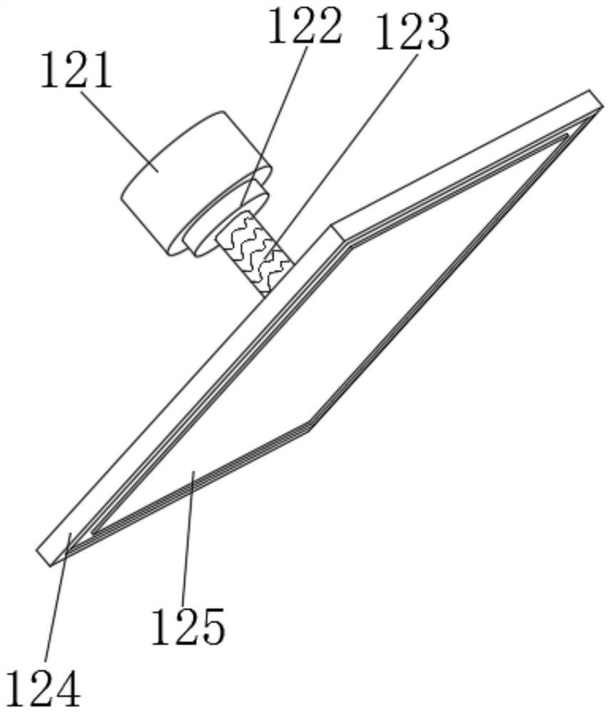
The invention discloses a large-capacity high-reliability rapid switching device which comprises a protection box, supporting columns are fixedly connected to the four corners of the lower end of the protection box correspondingly, a plurality of heat dissipation grooves are formed in the left end and the right end of the protection box correspondingly, a box cover is fixedly connected to the upper end of the protection box, and fixing caps are fixedly connected to the four corners of the upper end of the box cover correspondingly. A stabilizing device is movably connected to the middle of the upper end of the box cover, four supporting legs are fixedly connected to the lower box wall of the protection box, a main body device is connected to the inner side of the fixed box in a penetrating and inserting mode, a box door is movably connected to the front end of the protection box through a hinge, and a transparent cover is fixedly connected to the front end of the box door. A handle is fixedly connected to the right portion of the front end of the box door, and a rear frame is fixedly connected to the middle of the rear end of the protection box. According to the large-capacity high-reliability rapid switching device, the whole device is reasonable in structural design, rapid switching use is achieved, the structure is stable, reliability is high, and the large-capacity high-reliability rapid switching device is suitable for wide application.

Description

technical field [0001] The invention relates to the related field of power supply, in particular to a large-capacity, high-reliability and fast switching device. Background technique [0002] In the event of an unexpected power failure, the machine will stop running, making the machine run discontinuously. To this end, a rapid switching device for backup power that extends battery life is developed. The device is switched quickly, so that it can continue to work when encountering a power failure, ensuring the continuity of the machine operation. The inventor found that at least the following problems have not been solved in the prior art: 1. When the existing power supply is switched, it is not Able to perform fast switching, otherwise it is easy to cause instantaneous disconnection, resulting in data loss; 2. The existing switching device is prone to shaking during the switching process, and the stability of use is poor; 3. During the use of the existing switching device, ...

Claims


Application Information

Patent Timeline
Patent Type & Authority Applications(China)
IPC IPC(8): H01H9/22H02J9/06
CPCH01H9/22H02J9/068Y04S20/20
Inventor 黄焌洪
Owner 南京竣望新材料有限公司
Learn More