
Electronic device

A technology for electronic equipment and casings, applied in the field of electronic equipment, can solve the problems of reducing practical performance, sacrificing the sound-emitting performance of sound-emitting devices, and complex structural design of sound-emitting devices, and achieves the effect of simplifying structure, realizing light and thin design, and reducing size

Pending Publication Date: 2022-05-17
GOERTEK INC
View PDF0 Cites 0 Cited by
  • Summary
  • Abstract
  • Description
  • Claims
  • Application Information

AI Technical Summary

Problems solved by technology

However, in the miniaturization design of electronic equipment in the prior art, there is generally the problem of sacrificing the sounding performance of the sounding device, and the structural design of the sounding device is relatively complicated in order to meet the miniaturization design, thereby greatly reducing the Practical performance

Method used


Image

  • Electronic device
  • Electronic device
  • Electronic device

Examples


Embodiment Construction

[0057] The following will clearly and completely describe the technical solutions in the embodiments of the present invention with reference to the accompanying drawings in the embodiments of the present invention. Obviously, the described embodiments are only part of the embodiments of the present invention, not all of them. Based on the embodiments of the present invention, all other embodiments obtained by persons of ordinary skill in the art without creative efforts fall within the protection scope of the present invention.

[0058] It should be noted that all directional indications (such as up, down, left, right, front, back...) in the embodiments of the present invention are only used to explain the relationship between the components in a certain posture (as shown in the accompanying drawings). Relative positional relationship, movement conditions, etc., if the specific posture changes, the directional indication will also change accordingly.

[0059] At the same time,...


PUM


Abstract

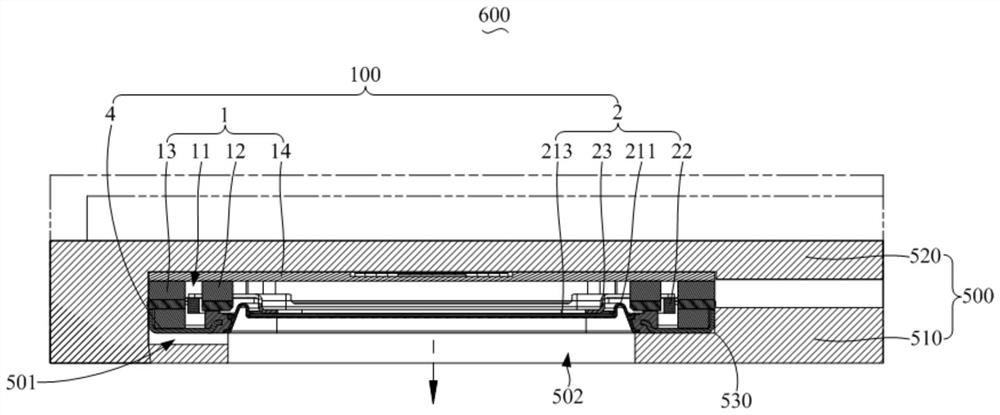
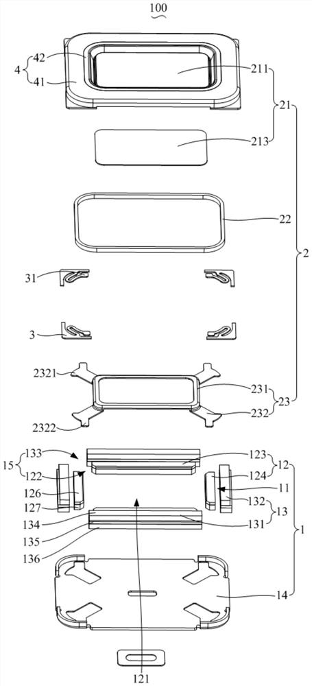
The invention discloses electronic equipment which comprises a machine shell and a sound production device, an installation cavity is formed in the machine shell, the machine shell is further provided with a sound outlet communicated with the installation cavity, the sound production device is arranged in the installation cavity, the sound production device comprises a magnetic circuit system and a vibration system, the magnetic circuit system is provided with a magnetic gap, the magnetic circuit system is arranged in a hollow mode, and the vibration system is arranged in the installation cavity. The vibration system is arranged in the magnetic gap to define a containing space, the vibration system comprises a vibrating diaphragm assembly, a voice coil and a framework, the vibrating diaphragm assembly is located in the containing space, the voice coil is inserted in the magnetic gap, one end of the framework is connected with the vibrating diaphragm assembly, and the other end of the framework extends into the magnetic gap and is connected with the voice coil; wherein the vibrating diaphragm assembly is arranged opposite to the sound outlet. According to the electronic equipment provided by the invention, the vibration radiation surface of the sound production device is placed in the middle of the magnetic circuit system, and the voice coil is connected with the vibration radiation surface through the framework to transmit the motion load, so that the thickness size of the sound production device is greatly reduced, the high-frequency resonance is effectively reduced, the acoustic performance is improved, and the processing and the assembly are convenient.

Description

technical field [0001] The invention relates to the technical field of electroacoustic conversion, in particular to an electronic device. Background technique [0002] With the rapid development of science and technology, people have higher and higher requirements for the sound quality of electronic equipment. The requirements for electronic equipment are not limited to the playback of video and audio, but also have higher requirements for the sound quality and reliability of the sound played by electronic equipment. Among them, the sound-generating device in the electronic equipment is affected by the appearance structure of the electronic equipment, and its volume is getting smaller and smaller. As an important and indispensable functional component of electronic equipment, the sound-generating device is an important part of the thin and light design of electronic equipment, so it is extremely important for the thin and light design of the sound-generating device. However...

Claims


Application Information

Patent Timeline
Patent Type & Authority Applications(China)
IPC IPC(8): H04R9/02H04R9/04H04R9/06H04R7/12
CPCH04R9/027H04R9/041H04R9/06H04R7/127
Inventor 郎贤忠刘松蔡晓东
Owner GOERTEK INC
Learn More