Control method of active clamp switch in bridge converter

A technology of clamping switch and control method, which is applied in the field of converters, can solve the problems of large effective value of current, poor clamping effect, and high peak value of resonant current of the primary side switch, and achieves reduction of effective value of current, simple control sequence, easy-to-achieve effects

Pending Publication Date: 2022-05-17
FSP POWERLAND TECH
View PDF2 Cites 0 Cited by
  • Summary
  • Abstract
  • Description
  • Claims
  • Application Information

AI Technical Summary

Problems solved by technology

However, the clamping effect achieved by this patent is not good. Although the clamping switch does not have a hard turn-on, it still has a hard turn-off, and it cannot assist the ZVS realization of the primary-side bridge arm switch, and cannot reduce the secondary-side switch synchronous rectification switch reverse recovery loss
[0004] The patent with the publication number US10277138B2 discloses an active clamp full-bridge converter and its driving method. The control mode of the active clamp circuit disclosed in this patent can realize the soft conduction of the hysteresis switch of the primary side and reduce the primary side during the circulation period. current, and can eliminate the reverse recovery problem of the secondary side rectifier switch, but the peak value of the resonant current of the primary side switch is high, and the effective value of the current is large, the current of the clamp switch is too large, and the clamp switch has relatively high requirements on the timing of the control high

Method used


Image

  • Control method of active clamp switch in bridge converter
  • Control method of active clamp switch in bridge converter
  • Control method of active clamp switch in bridge converter

Examples


Embodiment Construction

[0029] In order to make the purpose and technical solutions of the embodiments of the present invention more clear, the following will clearly and completely describe the technical solutions of the embodiments of the present invention in conjunction with the drawings of the embodiments of the present invention. Apparently, the described embodiments are some, not all, embodiments of the present invention. Based on the described embodiments of the present invention, all other embodiments obtained by persons of ordinary skill in the art without creative efforts shall fall within the protection scope of the present invention.

[0030] The terms "first", "second", "third", "fourth", etc. (if any) in the present invention are used to distinguish between similar elements and do not necessarily describe a specific order or sequence sequence of time. It is to be understood that the terms so used are interchangeable under appropriate circumstances such that the embodiments of the subje...


PUM


Abstract

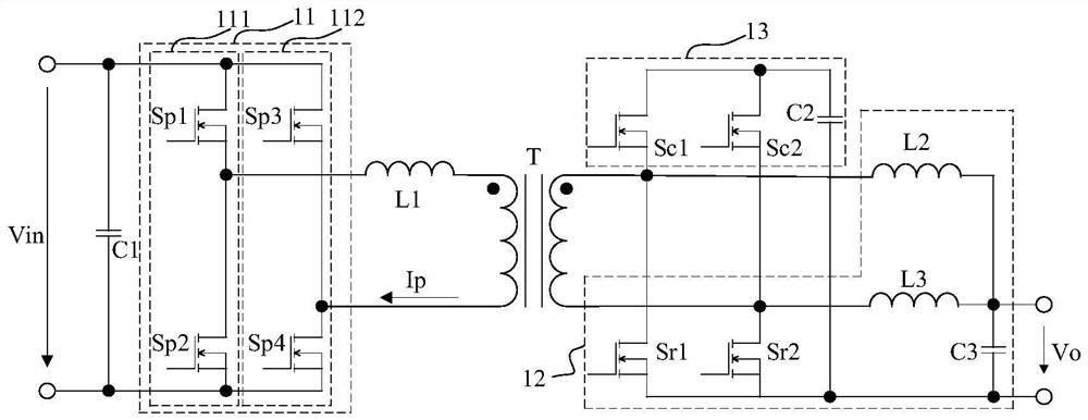
The invention provides an active clamping full-bridge converter and a control method thereof.The active clamping full-bridge converter comprises a transformer, a primary side circuit connected with a primary side winding of the transformer and a secondary side circuit connected with a secondary side winding of the transformer, and the secondary side circuit comprises an output rectifying circuit with a first switch and a second switch and a clamping circuit; the first switch and the second switch are connected with the two ends of the secondary winding after being connected in series, the clamping circuit comprises a first clamping switch, a second clamping switch and a clamping capacitor, and the first clamping switch and the second clamping switch are connected with the two ends of the secondary winding after being connected in series. One end of the clamping capacitor is connected with the series connection midpoint of the first clamping switch and the second clamping switch, and the other end of the clamping capacitor is connected with the series connection midpoint of the first switch and the second switch. According to the invention, zero-voltage switching-on of the lagging bridge arm can be realized, and the current effective values of the primary side switch and the secondary side switch can be effectively reduced.

Description

technical field [0001] The invention relates to the field of converters, in particular to a control method for an active clamp switch in a bridge converter. Background technique [0002] The full-bridge topology circuit has the characteristics of small current stress of semiconductor devices, high utilization rate of magnetic components, wide control range, high efficiency, and constant switching frequency. However, the full-bridge topology circuit also has inherent disadvantages, such as the ringing and voltage stress of the synchronous rectification switch, and the loss of zero-voltage switching under low load conditions is relatively large, so the switching frequency is limited. [0003] The patent with the publication number CN 208445482U discloses a control circuit for suppressing voltage oscillation on the secondary side of a phase-shifted full bridge. The control mode of the disclosed active clamp circuit is that when the secondary synchronous rectification switch is ...

Claims


Application Information

Patent Timeline
Patent Type & Authority Applications(China)
IPC IPC(8): H02M1/32H02M3/335H02M1/088
CPCH02M1/32H02M3/33592H02M1/088Y02B70/10
Inventor 孙巨禄徐明王磊王来振
Owner FSP POWERLAND TECH
Why Eureka
Try Eureka