
Patsnap Eureka
For R&D, Patsnap Eureka makes reading and utilizing patents & technical documents easy.
Patsnap Eureka AIR
Designed for self-driven R&D workflows. Generate viable solutions, solve complex R&D challenges, empower your innovation with AI.

Patsnap Eureka Materials
Designed for material experts only. Revolutionize your material R&D, from search, analyze, to developing new materials.

TechResearch
Generate reliable direction feasibility study reports for your R&D in just a few steps.

TechSeek
Discover and master advanced knowledge NOW. Basics, ideas, possibilities, all at once.

TechMind
As an expert in R&D Theories, TechMind can generates customized viable solutions instantly.

TechRisk
Analyze your overall solution with one click, know your potential R&D risks in advance.

TechMonitor
Get weekly tech updates, stay abreast of the latest tech innovations and key insights.
Drilling equipment for aluminum alloy manufacturing
A technology of drilling equipment and aluminum alloy, applied in the field of aluminum alloy manufacturing, can solve the problems of no cooling mechanism, affecting the efficiency of opening holes, and high temperature of the drill bit, and achieve the effect of avoiding the deterioration of the cooling effect.
- Summary
- Abstract
- Description
- Claims
- Application Information
AI Technical Summary
Problems solved by technology
Method used
Image

Examples
Embodiment 1
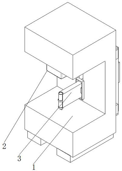
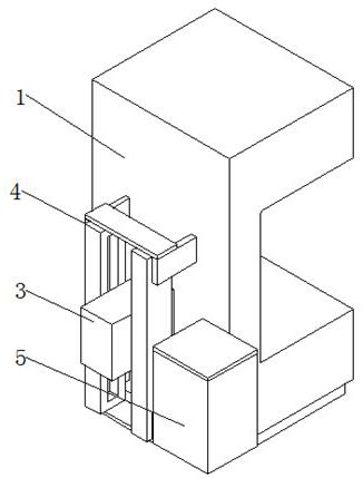
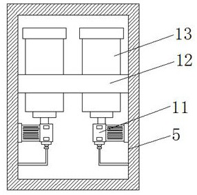
[0026] refer to Figure 1-5 , a kind of drilling equipment for aluminum alloy manufacturing, including a drill floor 1, an opening is opened on one side of the outer wall of the drill floor 1, and a fixture table 2 is fixedly connected to the top inner wall of the opening, and a rectangular opening is opened on the inner wall of one side of the opening. The inner wall of the opening is slidingly connected with a driving mechanism 3, and the outer wall of one side of the drill floor 1 is fixedly connected with two electric slide rails-4, and the driving mechanism 3 is slidingly connected on the inner walls of the two electric slide rails-4. The side outer wall is fixedly connected with the equipment box 5, the drive mechanism 3 includes the drive box 6, and the inner wall of the drive box 6 is slidably connected with the drive plate 16, and the one side outer wall of the drive plate 16 is fixedly connected with the drive column 7, and one end of the drive column 7 There is an a...
Embodiment 2
[0029] refer to Figure 1-4 And 6, a kind of drilling equipment for aluminum alloy manufacturing, comprising a drill floor 1, an opening is opened on one side of the outer wall of the drill floor 1, and a fixture table 2 is fixedly connected to the top inner wall of the opening, and a rectangular opening is opened on the inner wall of one side of the opening , the inner wall of the rectangular opening is slidably connected with a drive mechanism 3, and the outer wall of one side of the drill floor 1 is fixedly connected with two electric slide rails-4, and the drive mechanism 3 is slidably connected with the inner walls of the two electric slide rails-4, and the drill floor 1 One side outer wall of one side is fixedly connected with equipment box 5, and driving mechanism 3 comprises driving box 6, and the inner wall of driving box 6 is slidably connected with driving board 16, and one side outer wall of driving board 16 is fixedly connected with driving post 7, and driving post...
PUM
 Abstract
Description
Claims
Application Information
 - R&D Engineer
- R&D Manager
- IP Professional
- Industry Leading Data Capabilities
- Powerful AI technology
- Patent DNA Extraction
Browse by: Latest US Patents, China's latest patents, Technical Efficacy Thesaurus, Application Domain, Technology Topic, Popular Technical Reports.
© 2024 PatSnap. All rights reserved.Legal|Privacy policy|Modern Slavery Act Transparency Statement|Sitemap|About US| Contact US: help@patsnap.com