Discharging device of clinker sampler and use method of discharging device

A technology of unloading device and sampler, applied in the direction of sampling device and other directions, can solve the problems of reducing the effect of sampling, unable to realize centralized sampling, increasing cost, etc., and achieving the effect of improving the effect of sampling

Pending Publication Date: 2022-05-13
襄阳中圣达机电科技有限公司
View PDF0 Cites 0 Cited by
  • Summary
  • Abstract
  • Description
  • Claims
  • Application Information

AI Technical Summary

Problems solved by technology

[0005] Aiming at the deficiencies of the prior art, the present invention provides a clinker sampler unloading device and its use method, which solves the problem that the existing sampler will directly take the materials taken inside the sampler during the sampling process. As a result, the sampler is used to form a passage between the chute and the storage tank, and the feeding and taking of the sampler cannot be processed individually, so that it is impossible to achieve periodic sampling, which reduces the sampling rate to a certain extent. effect, and because the scope of the sampling hole on the chute is relatively large, it is easy to cause some materials inside the chute to slide into the connecting seat between the sampler and the sampling end of the chute under the influence of inertia, so that the remaining part of the material in this section (these The material is not sampled and exported by the sampler), and centralized sampling cannot be realized, resulting in a waste of materials and increasing the cost

Method used


Image

  • Discharging device of clinker sampler and use method of discharging device
  • Discharging device of clinker sampler and use method of discharging device
  • Discharging device of clinker sampler and use method of discharging device

Examples


Embodiment Construction

[0029] In order to make the purpose, technical solutions and advantages of the embodiments of the present invention clearer, the technical solutions in the embodiments of the present invention will be clearly and completely described below in conjunction with the drawings in the embodiments of the present invention. Obviously, the described embodiments It is a part of embodiments of the present invention, but not all embodiments. Based on the embodiments of the present invention, all other embodiments obtained by persons of ordinary skill in the art without creative efforts fall within the protection scope of the present invention.

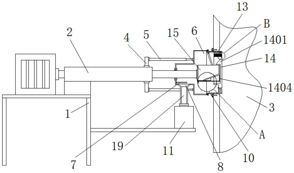
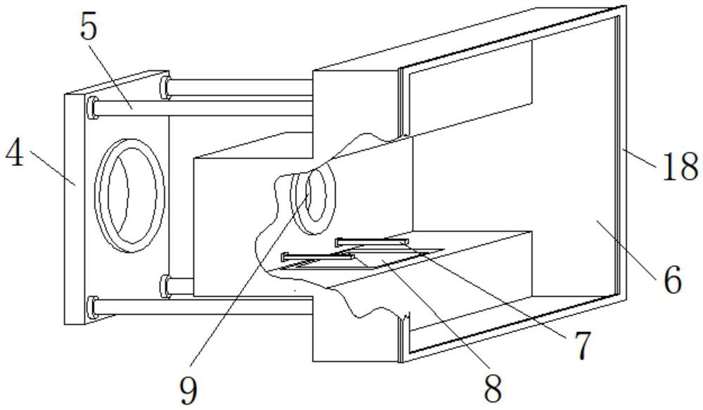
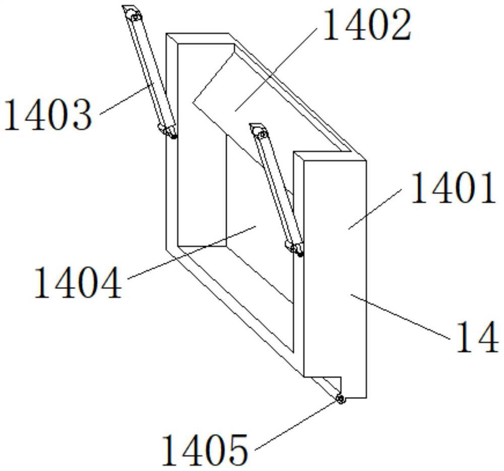
[0030] see Figure 1-7: A kind of unloading device of clinker sampler, comprises underframe 1, and one side of underframe 1 top is equipped with first cylinder 2, and one side outside first cylinder 2 is provided with support block 4, and one side of support block 4 The two ends of the top and the bottom are all equipped with a second cylinder 5,...


PUM


Abstract

The invention relates to the technical field of clinker sampling and discharging, and discloses a clinker sampler discharging device which comprises a bottom frame, a first air cylinder is installed on one side of the top of the bottom frame, a supporting block is arranged on one side of the outer portion of the first air cylinder, and second air cylinders are installed at the two ends of the top and the two ends of the bottom of one side of the supporting block correspondingly. A protective cover is arranged at the output end of the second air cylinder, a material guiding opening is formed in one side of the bottom end in the protective cover, and push rods are arranged at the two ends of the bottom of one side in the protective cover. According to the sampling device, the partition plates are arranged on the two sides of the baffle through the pressing groove, materials passing through the material holes are intensively guided into the material collecting groove along the positions, exposed at the top of the baffle, of the material holes, the situation that part of the materials in the elephant trunk slide into the connecting base between the sampler and the sampling end of the elephant trunk due to inertia is avoided, and concentrated sampling is achieved; the waste of the materials is avoided, and the consumption of part of the materials in the sampling process is reduced.

Description

technical field [0001] The invention relates to the technical field of clinker sampling and unloading, in particular to a clinker sampler unloading device and a use method thereof. Background technique [0002] The clinker sampler is used for continuous sampling of powdery materials such as raw meal leaving the mill, raw meal entering the kiln, pulverized coal leaving the mill, pulverized coal entering the kiln, cement leaving the mill, and cement leaving the factory. [0003] However, in the process of sampling, the existing sampler will directly lead the material taken inside the sampler directly into the storage tank, so that a passage is formed between the chute and the storage tank by using the sampler, and it is impossible to make the sampler The feeding and retrieving materials are processed individually, so that it is impossible to realize staged sampling, which reduces the sampling effect to a certain extent, and because the sampling holes on the chute have a large ...

Claims


Application Information

Patent Timeline
Patent Type & Authority Applications(China)
IPC IPC(8): G01N1/20
CPCG01N1/20
Inventor 倪劲杰黄志杰倪明新黄念念
Owner 襄阳中圣达机电科技有限公司
Why Eureka
Try Eureka