Heat pump system, control method and air conditioner

A heat pump system and control method technology, applied in ventilation systems, heating methods, air conditioning systems, etc., can solve problems such as difficulty in defrosting and energy waste, and achieve the effect of reducing operating costs and optimizing power resource allocation

Active Publication Date: 2022-05-13
GREE ELECTRIC APPLIANCES INC
View PDF4 Cites 0 Cited by
  • Summary
  • Abstract
  • Description
  • Claims
  • Application Information

AI Technical Summary

Problems solved by technology

[0003] In view of this, the present invention provides a heat pump system, a control method and an air conditioner, through a water circulation circuit, a heat storage unit, a first refrigerant circulation circuit and a second The combination of refrigerant circulation loops solves the problems of energy waste and difficult defrosting in traditional methods

Method used


Image

  • Heat pump system, control method and air conditioner
  • Heat pump system, control method and air conditioner
  • Heat pump system, control method and air conditioner

Examples


Embodiment 1

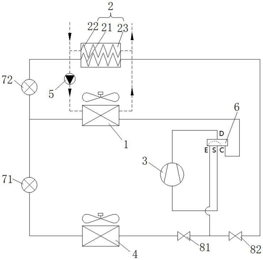
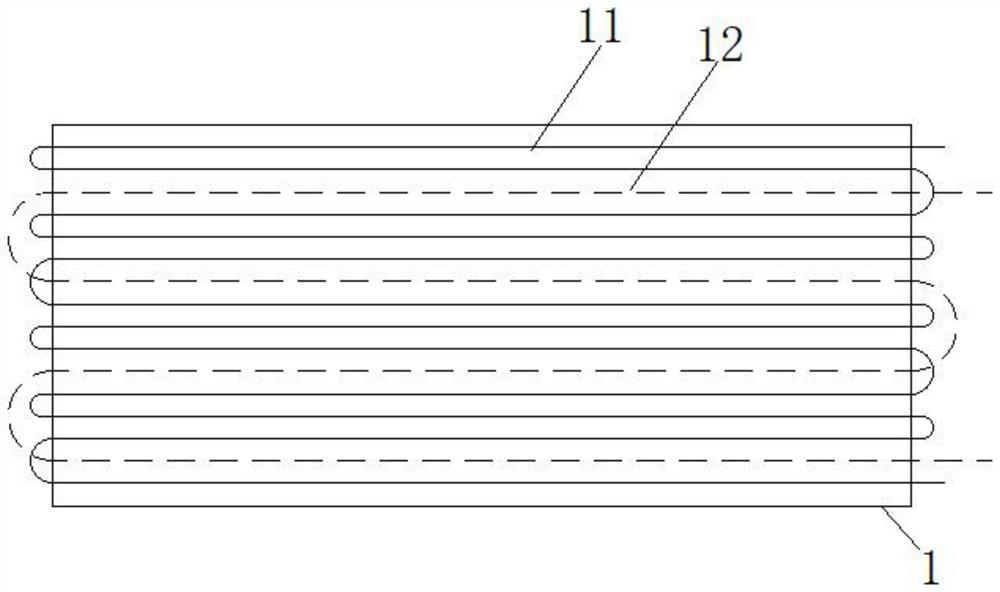
[0039] This embodiment provides a heat pump system, such as figure 1 As shown, the heat pump system includes an outdoor heat exchanger 1 with a first refrigerant pipeline 11 and a first water pipeline 12, a heat storage unit 2 with a second refrigerant pipeline 21 and a second water pipeline 22, and the first water pipeline Road 12 communicates with the second water pipeline 22 to form a water circulation loop; it also includes a compressor 3 and an indoor heat exchanger 4, and the compressor 3, the first refrigerant pipeline 11 and the indoor heat exchanger 4 form a first refrigerant circulation loop, The compressor 3 , the first refrigerant pipeline 11 and the second refrigerant pipeline 21 form a second refrigerant circulation loop.

[0040] Specifically, there are two pipeline systems in the outdoor heat exchanger 1 and the heat storage unit 2, respectively carrying refrigerant and water; it is precisely because there are two pipeline systems in the outdoor heat exchanger ...

Embodiment 2

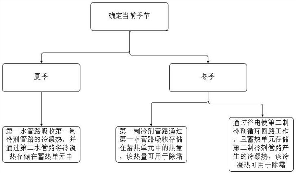
[0061] This embodiment provides a control method for a heat pump system, the control method is used to control the heat pump system in Embodiment 1, such as image 3 shown, including:

[0062] In summer, both the first refrigerant circulation loop and the water circulation loop work, and the first water pipeline 12 absorbs the condensation heat of the first refrigerant pipeline 11, and stores the condensation heat in the thermal storage unit 2 through the second water pipeline 22 ; And the heat of condensation stored in the heat storage unit 2 is used to provide domestic hot water;

[0063] In winter, the second refrigerant circulation loop is operated by valley electricity, and the thermal storage unit 2 stores the condensation heat generated by the second refrigerant pipeline 21; and the condensation heat stored in the thermal storage unit 2 is used for defrosting.

[0064] In this way, this embodiment uses the condensation heat in summer to provide domestic hot water for u...

Embodiment 3

[0066] This embodiment provides an air conditioner, and the air conditioner includes the heat pump system of Embodiment 1.


PUM

PropertyMeasurementUnit
Phase transition temperatureaaaaaaaaaa

Abstract

The invention belongs to the technical field of heat pumps, and relates to a heat pump system, a control method and an air conditioner, the heat pump system comprises an outdoor heat exchanger with a first refrigerant pipeline and a first water pipeline, and a heat storage unit with a second refrigerant pipeline and a second water pipeline, and the first water pipeline and the second water pipeline are communicated to form a water circulation loop; the compressor, the first refrigerant pipeline and the indoor heat exchanger form a first refrigerant circulation loop, and the compressor, the first refrigerant pipeline and the second refrigerant pipeline form a second refrigerant circulation loop. Condensation heat in summer is stored in the heat storage unit through the water circulation loop and the first refrigerant circulation loop to be used for providing hot water, and the problems of heat pollution and energy waste caused by the fact that heat is discharged into air are solved. The low-cost valley electricity in winter is stored in the heat storage unit in a heat form through the water circulation loop and the second refrigerant circulation loop and used for defrosting of the outdoor heat exchanger, the indoor temperature cannot be fluctuated during defrosting, and the effect of reducing the operation cost can be achieved.

Description

technical field [0001] The invention belongs to the technical field of heat pumps, and in particular relates to a heat pump system, a control method and an air conditioner. Background technique [0002] Air source heat pump is an efficient, energy-saving and environmentally friendly energy utilization method, which has been more and more widely used. It not only causes energy waste, but also brings heat pollution to the air; and when the temperature is low in winter, the outdoor heat exchanger is prone to frost and needs to be defrosted. Generally, the four-way valve reverse cycle defrost is used to change the heating cycle. It is a refrigeration cycle, which has the problems of long defrosting time and excessive fluctuation of indoor temperature. Contents of the invention [0003] In view of this, the present invention provides a heat pump system, a control method, and an air conditioner, through the combination of a water circulation loop, a heat storage unit, a first r...

Claims


Application Information

Patent Timeline
IPC IPC(8): F25B29/00F25B47/02F25B41/40F25B41/20F25B41/30F25B49/02F24F5/00F24F12/00F24F11/42
CPCF25B29/003F25B47/02F25B41/40F25B41/20F25B41/30F25B49/02F24F5/001F24F5/0021F24F12/00F24F11/42Y02E60/14
Inventor 方金升梁祥飞徐箐周孙希
Owner GREE ELECTRIC APPLIANCES INC
Why Eureka
Try Eureka