
Novel speed reducer device

A reducer, a new type of technology, applied in the direction of transmission parts, mechanical equipment, gear lubrication/cooling, etc., can solve the problems of excessive consumption of lubricating oil, poor lubrication effect, large friction, etc., to solve the problem of excessive consumption of lubricating oil , Easy to install and disassemble the effect of the rotating shaft

Pending Publication Date: 2022-05-13
江苏省同济科技有限公司
View PDF0 Cites 0 Cited by
  • Summary
  • Abstract
  • Description
  • Claims
  • Application Information

AI Technical Summary

Problems solved by technology

[0004] In order to make up for the deficiencies of the existing technology and solve the problem that the lubricating oil is consumed too quickly, the lubrication effect between the gears is deteriorated, the friction between the gears is relatively large, and the service life of the gears is reduced, the present invention proposes a New reducer device

Method used


Image

  • Novel speed reducer device
  • Novel speed reducer device
  • Novel speed reducer device

Examples


Embodiment 1

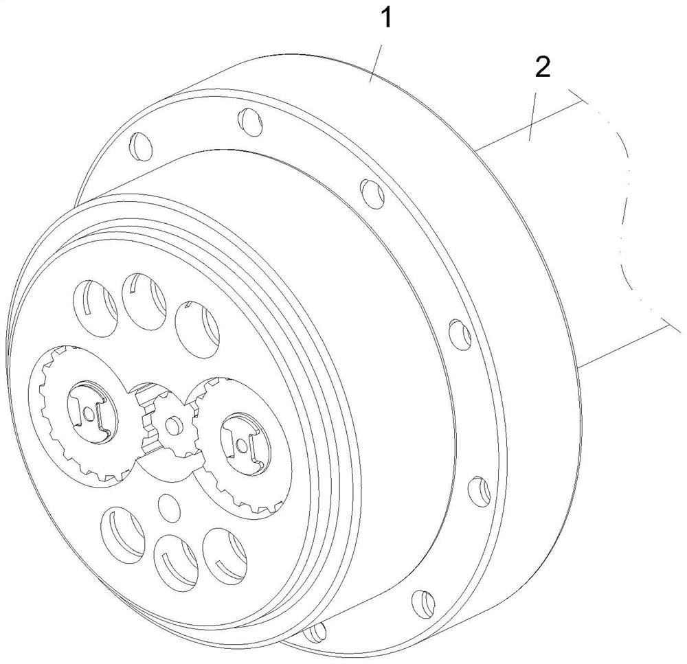
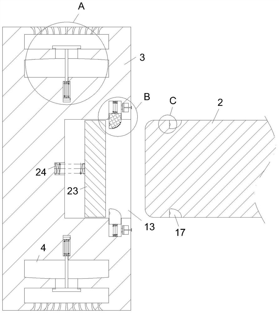
[0027] see Figure 1-6 As shown, a new type of reducer device includes a reducer body 1; a drive gear 3 is installed inside the reducer body 1; a plunger groove 13 is provided on the side of the drive gear 3; The inside of the reducer body 1 is equipped with a rotating shaft 2 through a fixed assembly; the inside of the reducer body 1 is provided with an oil storage chamber 4; the oil storage chamber 4 is ring-shaped and opened inside the reducer body 1; There are several oil outlet chambers 5 inside, and they are regularly arranged in a circular array; an oil hole 51 is opened between the oil storage chamber 4 and the oil outlet chamber 5; an oil baffle 6 is provided on the oil hole 51 The side wall of the oil baffle plate 6 is fixedly connected with a connecting rod 7; the end of the connecting rod 7 is fixedly connected with a first fixed block 9; the inside of the driving gear 3 is provided with a first sliding chamber 8; The first fixed block 9 is slidably connected insi...

Embodiment 2

[0036] see Figure 7 As shown in Comparative Example 1, as another embodiment of the present invention, the side wall of the sliding block 19 is fixed with a leak-proof gasket 30; 18 contacts; during work, when the sliding block 19 pumps air to the inside of the second sliding chamber 14, the leak-proof cushion layer 30 can make the sealing of the sliding block 19 stronger, thereby making the pumping effect of the sliding block 19 better.

[0037] Working principle, when working, when the reducer needs to be used, the rotating shaft 2 can be fixed inside the insertion rod groove 13, and then when the driving gear 3 rotates, the centrifugal force can drive the oil baffle plate 6 to the oil outlet chamber 5 direction, so that the lubricating oil inside the oil storage chamber 4 enters the inside of the oil outlet chamber 5, and then the lubricating oil flows out through the oil outlet hole 11, and the lubricating oil can lubricate between the driving gear 3 and the rest of the g...


PUM


Abstract

The invention belongs to the technical field of speed reducers, and particularly relates to a novel speed reducer device which comprises a speed reducer body. A driving gear is mounted in the speed reducer body; an inserting rod groove is formed in the side surface of the driving gear; a rotating shaft is mounted in the rod inserting groove through a fixing assembly; an oil storage cavity is formed in the speed reducer body; the oil storage cavity is annularly formed in the speed reducer body; a plurality of oil outlet cavities are formed in the speed reducer body and are regularly arranged in a circumferential array; through the structural design that the centrifugal force drives the oil baffle plate to move towards the oil outlet cavity, lubricating oil in the oil storage cavity enters the oil baffle plate and flows out through the oil outlet hole, the function of continuously supplying oil in the rotating process of the driving gear is achieved, and therefore the problems that the lubricating oil is consumed too fast, and the service life is prolonged are effectively solved. And the friction force between the gears is large.

Description

technical field [0001] The invention relates to the technical field of reducers, in particular to a novel reducer device. Background technique [0002] The RV reducer is a new type of reducer composed of the front stage of the planetary gear reducer and the rear stage of the cycloidal pinwheel reducer. It has the advantages of compact structure and large transmission ratio. [0003] During the use of the reducer, due to the need for a fast gear speed, it is easy to consume too much lubricating oil, resulting in poor lubrication between the gears, resulting in greater friction between the gears, resulting in gear wear The service life is reduced; therefore, a new type of reducer device is proposed to solve the above problems. Contents of the invention [0004] In order to make up for the deficiencies of the existing technology and solve the problem that the lubricating oil is consumed too quickly, the lubrication effect between the gears is deteriorated, the friction betwe...

Claims


Application Information

Patent Timeline
IPC IPC(8): F16H57/04F16H57/023
CPCF16H57/0427F16H57/043F16H57/023F16H2057/0235
Inventor 金仁瀚
Owner 江苏省同济科技有限公司
Learn More