Silt remover pipe head for hydraulic engineering design

A water conservancy project and desilting machine technology, which is applied in the direction of earth mover/shovel, mechanically driven excavator/dredger, construction, etc., can solve the problem of blocking the feed inlet, so as to avoid blockage and improve passability , the effect of improving efficiency

Active Publication Date: 2022-05-13
合肥海博工程设计集团有限公司
View PDF6 Cites 0 Cited by
  • Summary
  • Abstract
  • Description
  • Claims
  • Application Information

AI Technical Summary

Problems solved by technology

[0003] However, the existing dredging pipe head often has the trouble of blocking the feed inlet due to aquatic plants during the dredging process. In order to solve this technical problem, a dredging machine pipe head for water conservancy engineering design is proposed.

Method used


Image

  • Silt remover pipe head for hydraulic engineering design
  • Silt remover pipe head for hydraulic engineering design
  • Silt remover pipe head for hydraulic engineering design

Examples


Embodiment 1

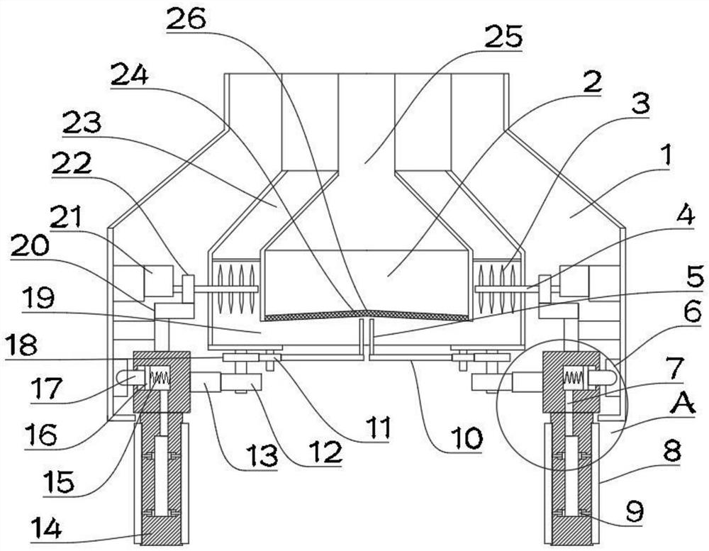
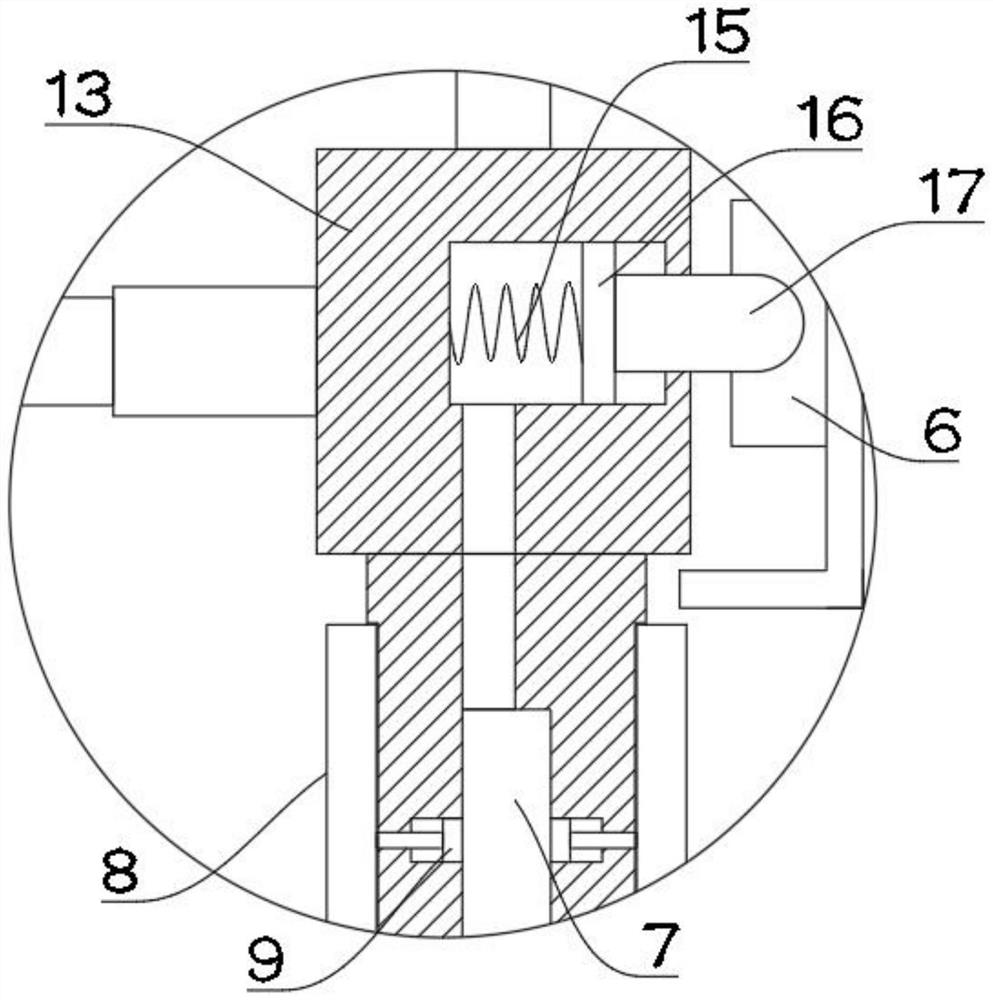
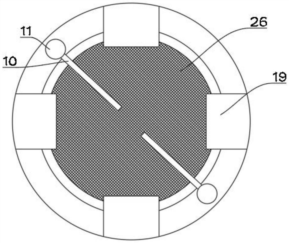
[0031] see Figure 1 ~ Figure 3 , in Embodiment 1 of the present invention, a structural diagram of a pipe head of a dredging machine for water conservancy engineering design provided by the embodiment of the present invention, including: a support shell 1; a suction head for absorbing silt is provided inside the support shell 1 2. The middle position of the bottom of the absorption head 2 is provided with a main adsorption port 24 for absorbing silt, and the outer array of the main adsorption port 24 is provided with a plurality of auxiliary inlets 19, and the auxiliary inlets 19 are used for absorbing aquatic plants;

[0032] A plurality of installation rods 14 arranged on the outside of the absorption head 2 in a circular array, and a plurality of crushing knives 8 are arranged in an array on the installation rod 14; the installation rods 14 are installed on the second gear ring 13, and the second The gear ring 13 is rotatably arranged inside the supporting shell 1; a plura...

Embodiment 2

[0037] see Figure 1 ~ Figure 3The main difference between this embodiment 2 and embodiment 1 is that in order to be able to treat aquatic plants and prevent clogging, the auxiliary adsorption channel 23 is provided with a crushing assembly. The crushing assembly includes a crushing shaft 4 rotatably mounted on the absorption head 2 , the surface of the crushing shaft 4 is provided with a plurality of crushing teeth 3 in an array, and the crushing teeth 3 are arranged inside the auxiliary adsorption flow channel 23 . In this way, the rotation of the crushing shaft 4 drives the rotation of the absorption head 2, thereby enabling the crushing teeth 3 to crush aquatic plants.

[0038] The suction head 2 is connected with a negative pressure pump for providing negative pressure to the main adsorption channel 25 and the auxiliary adsorption channel 23 .

[0039] Such as figure 1 , 2 As shown, as a preferred embodiment of the present invention, in order to drive the second gear r...


PUM


Abstract

The invention is suitable for the technical field of hydraulic engineering equipment, and provides a silt remover pipe head for hydraulic engineering design. Comprising a support housing; the absorption head is arranged in the supporting shell and used for absorbing sludge; a main adsorption opening used for adsorbing sludge is formed in the middle of the bottom of the absorption head, and a plurality of auxiliary inlets are formed in the outer side of the main adsorption opening in an array mode and used for absorbing aquatic plants; the mounting rods are arranged on the outer side of the absorption head in a circumferential array mode, and a plurality of crushing cutters are arranged on the mounting rods in an array mode; the mounting rod is mounted on the second gear ring, and the second gear ring is rotationally arranged in the supporting shell; the multiple crushing cutters intermittently extend out of the interior of the mounting rod in the rotating process; the swing rod is arranged on the absorption head in an intermittent swing mode, a scraping rod is arranged at the first end of the swing rod, the scraping rod is attached to the surface of the first filter screen, and the swing rod conveys aquatic plants on the surface of the first filter screen into the auxiliary inlet in the intermittent rotation process.

Description

technical field [0001] The invention relates to the technical field of water conservancy engineering equipment, in particular to a pipe head of a desilting machine for water conservancy engineering design. Background technique [0002] Sediment collects into rivers and reservoirs with water flow and often forms silt, which can easily cause channel blockage and seriously affect the use function of the river channel. If the river is not cleaned for a long time, it will be blocked, which will cause the water flow in the river to be blocked, and then there will be no water source in the downstream of the river. Therefore, it is necessary to use river dredging equipment to clean the river. The most important cleaning equipment for river dredging equipment is dredging Silt machine head. [0003] However, the existing dredging pipe head often has the problem of blocking the feed inlet due to aquatic plants during the dredging process. In order to solve this technical problem, a dr...

Claims


Application Information

Patent Timeline
Patent Type & Authority Applications(China)
IPC IPC(8): E02F3/92E02F5/28
CPCE02F3/92E02F3/9268E02F3/9275E02F3/9293E02F5/28E02F5/282
Inventor 万晓锐张仲伯刘建军吕蒙蒙
Owner 合肥海博工程设计集团有限公司
Why Eureka
Try Eureka