
Optical fiber winding device capable of effectively guiding uniform winding of optical fiber to avoid rewinding of optical fiber

A technology for a winding device and an optical fiber, applied in the field of optical fibers, can solve the problems of inconvenient storage and use of spools, inconvenient winding of optical fibers, and easy rewinding of optical fibers, so as to facilitate the replacement of spools and improve the utilization rate. , the effect of speeding up production

Pending Publication Date: 2022-05-13
李春田
View PDF7 Cites 0 Cited by
  • Summary
  • Abstract
  • Description
  • Claims
  • Application Information

AI Technical Summary

Problems solved by technology

[0005] Aiming at the deficiencies of the prior art, the present invention provides an optical fiber winding device that effectively guides the even winding of the optical fiber to avoid the rewinding of the optical fiber. The problem affects the advantages of optical fiber handling and solves the existing optical fiber winding device. Due to the long length of the optical fiber cable, the optical fiber can only be wound at a fixed position on the bobbin, so that the bobbin cannot be wound evenly , causing the other positions of the reel to be unusable, and it is also not convenient for the later storage and use of the reel, and the optical fiber is prone to rewinding during the rewinding process, which leads to the untightening of the reel, which affects the Problem of transportation to optical fiber cable

Method used

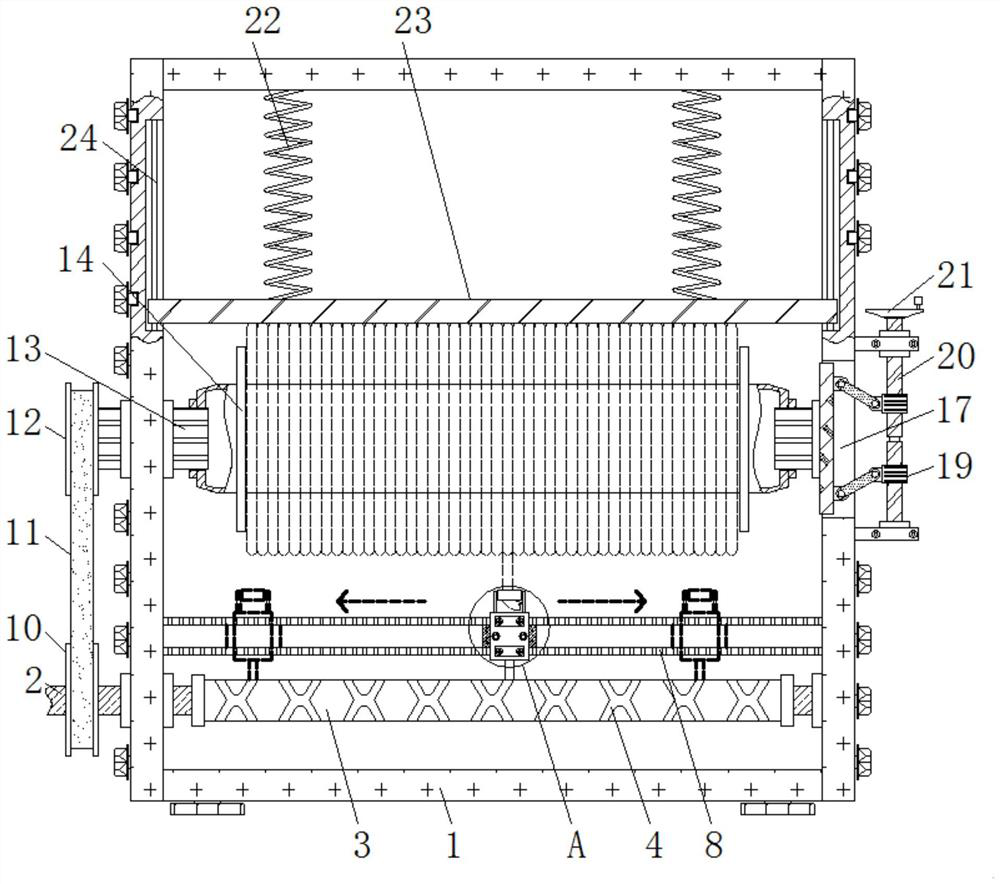
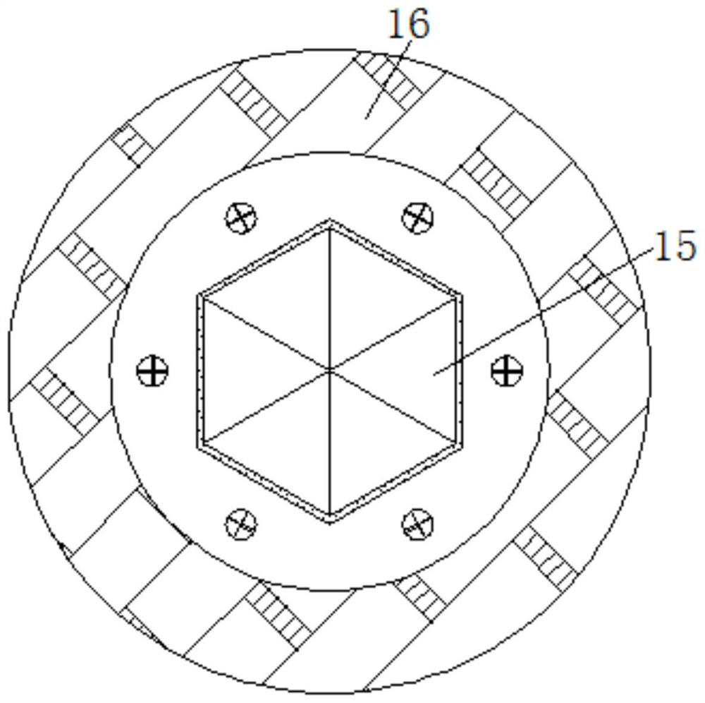
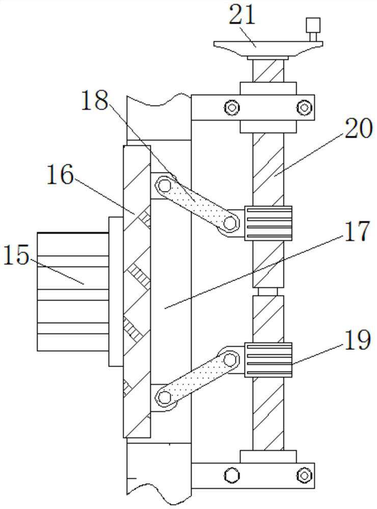

Image

  • Optical fiber winding device capable of effectively guiding uniform winding of optical fiber to avoid rewinding of optical fiber
  • Optical fiber winding device capable of effectively guiding uniform winding of optical fiber to avoid rewinding of optical fiber
  • Optical fiber winding device capable of effectively guiding uniform winding of optical fiber to avoid rewinding of optical fiber

Examples


Embodiment Construction

[0025] The following will clearly and completely describe the technical solutions in the embodiments of the present invention with reference to the accompanying drawings in the embodiments of the present invention. Obviously, the described embodiments are only some, not all, embodiments of the present invention. Based on the embodiments of the present invention, all other embodiments obtained by persons of ordinary skill in the art without making creative efforts belong to the protection scope of the present invention.

[0026] see Figure 1-4 , an optical fiber winding device that effectively guides the uniform winding of the optical fiber to avoid the rewinding of the optical fiber, comprising a housing 1, the inside of the housing 1 is movably connected to a driving shaft 2, and the left side of the driving shaft 2 is fixedly connected to a motor, not shown in the figure Specifically, the outer wall of the driving shaft 2 is fixedly connected with the active column 3, the o...


PUM


Abstract

The invention relates to the technical field of optical fibers, and discloses an optical fiber winding device capable of effectively guiding uniform winding of an optical fiber to avoid rewinding of the optical fiber, the optical fiber winding device comprises a shell, a driving shaft is movably connected in the shell, a driving column is fixedly connected to the outer wall of the driving shaft, and an annular groove is formed in the outer wall of the driving column. According to the optical fiber winding device capable of effectively guiding uniform winding of the optical fiber and avoiding rewinding of the optical fiber, the driving shaft rotates, and the optical fiber can be wound on the outer wall of the winding drum left and right, so that the effects of effectively guiding uniform winding of the optical fiber and improving the utilization rate of the winding drum are achieved. And under the action of the supporting spring, the pressing plate always compacts the optical fiber at the top of the winding drum, the problem of rewinding in the optical fiber fixing process is avoided, and therefore the effect of avoiding the problem of rewinding in the winding process and affecting optical fiber carrying is achieved. And when the rotating disc is rotated, the second edge rod can move left and right in the right side of the winding drum, so that the effects of conveniently replacing the winding reel and accelerating the production speed are achieved.

Description

technical field [0001] The invention relates to the field of optical fiber technology, in particular to an optical fiber winding device for effectively guiding an optical fiber to wind evenly and avoiding the rewinding of the optical fiber. Background technique [0002] As a mainstream way of broadband access, optical fiber has the advantages of large communication capacity, long relay distance, good confidentiality performance, strong adaptability, small size and light weight, wide source of raw materials and low price. Optical fiber cable is a communication Cable consisting of two or more glass or plastic optical fiber cores within a protective cladding covered by a plastic PVC outer sleeve. [0003] In the existing optical fiber winding device, due to the long length of the optical fiber cable, the optical fiber can only be wound at a fixed position on the bobbin, so that the bobbin cannot be rewound evenly, resulting in other positions of the bobbin It cannot be utilize...

Claims


Application Information

Patent Timeline
Patent Type & Authority Applications(China)
IPC IPC(8): B65H54/553B65H54/44B65H54/70B65H54/30G02B6/44
CPCB65H54/553B65H54/44B65H54/70B65H54/30G02B6/4457B65H2701/32
Inventor 李春田
Owner 李春田
Learn More