
Support plate glass arraying device with damage sensing function and arraying method

A technology of alignment devices and sensing devices, applied in the field of carrier glass alignment devices, can solve problems such as breakage, broken glass, glass scratches, etc., and achieve the effects of improving production efficiency, reducing damage rate, and improving reliability

Active Publication Date: 2022-05-13
青岛融合光电科技有限公司
View PDF8 Cites 0 Cited by
  • Summary
  • Abstract
  • Description
  • Claims
  • Application Information

AI Technical Summary

Benefits of technology

This patented technology helps prevent damage caused during transportation on high-pressure sodium lamps (HPS). It uses an improved way to detect if there are any cracks or defects along its surface before it breaks down due to pressure changes over time. By doing this with advanced sensors like cameras, these systems help identify small flaws early enough when they may be too big to handle safely.

Problems solved by technology

This technical problem addressed in this patents relates to finding ways to center carriers with their own equipment before they are shipped onto an auto assembling process. If there were any cracks that could occur while handling them, these damaged areas would have negative impact upon productivity and cost savings. Additionally, if no breaks happen at all, the entire columns can still work properly even though some parts might also get affected.

Method used


Image

  • Support plate glass arraying device with damage sensing function and arraying method
  • Support plate glass arraying device with damage sensing function and arraying method
  • Support plate glass arraying device with damage sensing function and arraying method

Examples


Embodiment 1

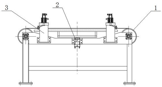
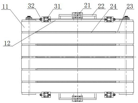
[0066] The alignment auxiliary mechanism 2 includes a cylinder driving mechanism, a brush fixing device, and a brush.

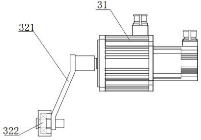
[0067] The positioning sensing device 3 of the carrier glass and the auxiliary mechanism 2 for the alignment include a servo motor 31 , a connecting sleeve, a swing arm 321 , a polyurethane wheel 322 and a complete mechanism fixing frame. In the present invention, the contact wheel with the carrier glass 4 is made of polyurethane material, which has a certain buffer force and reduces the breakage rate of the glass.

[0068] The working principle and process of the present invention: the carrier glass 4 is transported to the designated position by the parallel multi-section belt conveyor 1, at this time, the alignment auxiliary mechanism 2 installed at the bottom of the belt conveyor 1 acts, and the cylinder 21 rises. The top brush 24 is in contact with the carrier glass 4 and acts as a buffer. At this time, the four positioning sensing devices 3 driven by th...

Embodiment 2

[0070] The application process of the present invention is as follows: when the carrier glass 4 is placed on the multi-line parallel belt conveyor 1 with holes, the belt 11 rotates to transport the carrier glass 4 to the position shown in the figure, and the alignment auxiliary mechanism 2 operates, and the cylinder 21 Lift up to lift the carrier glass 4, at this moment, the four positioning sensing devices 3 driven by the servo motor 31 act, and the swing arm 321 rotates 90° from the vertical position, so that the polyurethane wheel 322 at the front end of the swing arm 321 is in contact with the carrier plate. The distance between the glass 4 is 0.5mm. At this time, the servo motor 31 is changed from position control to torque control, and the polyurethane wheel 322 will continue to move close to the glass. At this time, the change of the encoder position value of the servo motor 31 is used to sense whether it is damaged. If the position value changes more than 1mm, it will a...


PUM


Abstract

The invention relates to a carrier glass arraying device with a damage sensing function and an arraying method, and belongs to the technical field of OLED carrier glass post-processing. The device comprises a belt conveyor, an arraying auxiliary mechanism and a positioning sensing device, the arraying auxiliary mechanism is movably installed below the belt conveyor, the positioning sensing device is installed on the side of the belt conveyor, and the arraying auxiliary mechanism comprises an air cylinder installed on a support and an arraying frame controlled through lifting of the air cylinder; the positioning sensing device comprises a servo motor installed on the support and a sensing swing arm controlled through swing of the servo motor. The plate carrying glass is lifted to the position above the belt interval gap through the whole-column frame driven by the air cylinder; and the torque applied to the side edge by the polyurethane wheel is greater than the torque applied to the carrier plate glass by the top brush. The invention provides a method and a device capable of effectively reducing the alignment resistance, reducing the damage and sensing the damage in the alignment process for alignment positioning of the carrier glass, so that the operation reliability of a production line is improved.

Description


Claims


Application Information

Patent Timeline
Owner 青岛融合光电科技有限公司
Learn More