Intelligent unmanned aerial vehicle manufacturing device
A technology of unmanned aerial vehicles and manufacturing devices, which is applied in the direction of manufacturing tools, aircraft assembly, grinding drive devices, etc., can solve the problems of low manual grinding efficiency, falling risk and dust pollution on-site environment, etc., and achieve the effect of improving grinding efficiency
- Summary
- Abstract
- Description
- Claims
- Application Information
AI Technical Summary
Problems solved by technology
Method used
Image

Examples
Embodiment 1
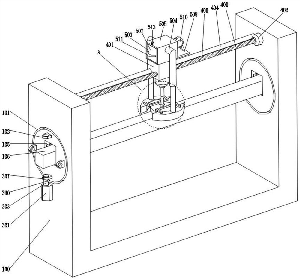
[0035] refer to Figure 1-7 A kind of intelligent unmanned aerial vehicle manufacturing device shown, comprises U-shaped seat 100, and the left and right side walls of U-shaped seat 100 are all provided with mounting holes 101, and the interior of two groups of mounting holes 101 is all provided with round block 102, two groups The inner wall of the mounting hole 101 is provided with an annular circular groove 103, and the outer surfaces of the two sets of circular blocks 102 are sleeved with annular limit blocks 104, and the two sets of annular limit blocks 104 are all arranged in the two sets of annular circular grooves 103, The insides of the two groups of round blocks 102 are all provided with placement grooves 105, the insides of the two groups of placement grooves 105 are inserted with bracket bodies 106, the insides of the two groups of round blocks 102 are all provided with clamping assemblies 200, and the outer parts of the left round blocks 102 are A turning assembly...
Embodiment 2
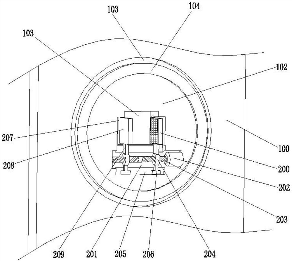
[0038] combine figure 1 and figure 2 As shown, based on the above-mentioned embodiment 1, the two sets of clamping assemblies 200 all include installation grooves 201 provided on the lower surfaces of the two sets of annular circular grooves 103, and the right sides of the two sets of installation grooves 201 are fixedly installed with the first motor 202, The output shafts of the two groups of first motors 202 are fixedly connected with reverse threaded rods 203, and the left sides of the two groups of reverse threaded rods 203 are rotatably connected with the left side walls of the two groups of mounting grooves 201, and the two groups of reverse threads The outer surfaces of the rods 203 are provided with two sets of nuts 204, and the inner walls of the four sets of nuts 204 are engaged and connected with the outer surfaces of the two sets of reverse threaded rods 203. The lower side walls of the two sets of mounting grooves 201 are A first limiting groove 205 is provided...
Embodiment 3
[0040] combine figure 1 , figure 2 and Figure 5 As shown, based on the above-mentioned embodiment 1 or 2, the turning assembly 300 includes a mounting block 301 fixedly installed on the left side of the U-shaped seat 100, the upper surface of the mounting block 301 is provided with a movable hole 302, and the inside of the movable hole 302 is inserted There is a first fixed rod 303, and the left and right side walls of the movable hole 302 are provided with second limiting grooves 304, and the insides of the two groups of second limiting grooves 304 are provided with second limiting blocks 305, and the two groups of second limiting grooves 304 are provided with second limiting blocks 305. The opposite surfaces of the limiting blocks 305 are all fixedly connected to the outer surface of the first fixed rod 303, and the outer surface of the first fixed rod 303 is fixedly equipped with two sets of pressing blocks 306, and the left side of the left round block 102 is equidistan...
PUM
 Abstract
Description
Claims
Application Information
 - R&D
- Intellectual Property
- Life Sciences
- Materials
- Tech Scout
- Unparalleled Data Quality
- Higher Quality Content
- 60% Fewer Hallucinations
Browse by: Latest US Patents, China's latest patents, Technical Efficacy Thesaurus, Application Domain, Technology Topic, Popular Technical Reports.
© 2025 PatSnap. All rights reserved.Legal|Privacy policy|Modern Slavery Act Transparency Statement|Sitemap|About US| Contact US: help@patsnap.com