
Rib cutter

A rib cutting machine and rib cutting technology, applied in the field of rib cutting machine, can solve the problems of not being able to store materials neatly, heavy manual labor, easy fatigue, etc., and achieve the effect of perfect rib cutting process, smooth processing process and high efficiency

Pending Publication Date: 2022-05-13
无锡市玉祁红光电子有限公司
View PDF0 Cites 0 Cited by
  • Summary
  • Abstract
  • Description
  • Claims
  • Application Information

AI Technical Summary

Problems solved by technology

[0003] The existing rib cutting equipment can complete the basic cutting action, but it does not have a high level of automation in the loading and unloading process, resulting in the need for manual auxiliary processing. Faced with a large number of rib trimming operations, the manual labor is very large, and it is easy to fatigue. Neatly store materials, which is inconvenient for the storage and subsequent access of small body materials, affecting the overall production capacity

Method used


Image

  • Rib cutter
  • Rib cutter
  • Rib cutter

Examples


Embodiment Construction

[0027] Embodiments of the present invention will be described in detail below, and examples of the embodiments are shown in the drawings, wherein the same or similar reference numerals denote the same or similar components or components having the same or similar functions throughout. The embodiments described below by referring to the figures are exemplary and are intended to explain the present invention and should not be construed as limiting the present invention.

[0028] In the description of the present invention, unless otherwise clearly stipulated and limited, the terms "connected", "connected" and "fixed" should be understood in a broad sense, for example, it can be a fixed connection, a detachable connection, or a mechanical connection. A connection can also be an electrical connection, a direct connection, or an indirect connection through an intermediary, or an internal connection between two elements or an interaction relationship between two elements. Those of o...


PUM


Abstract

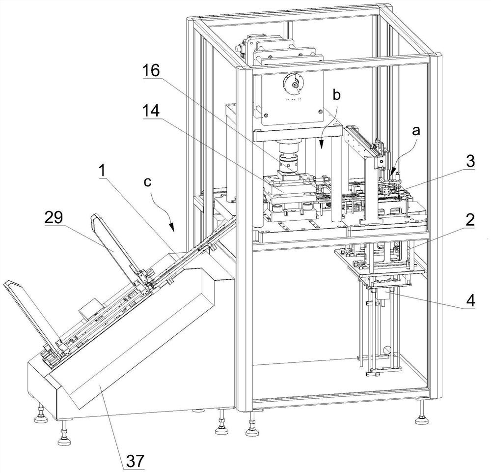
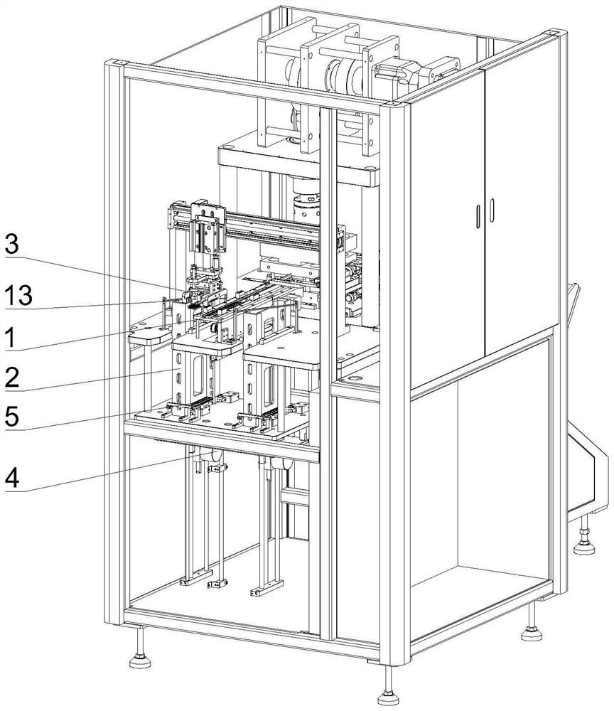
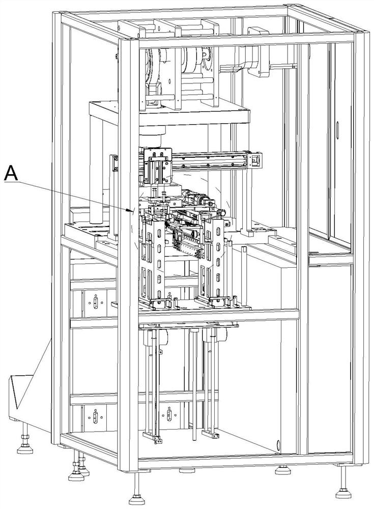
The invention discloses a rib cutting machine which comprises a material conveying slide way, the material conveying slide way is divided into a feeding area, a rib cutting area and a discharging area from front to back, a material storage box, a material taking hand and a material pushing mechanism are arranged in the feeding area, the material storage box is located on one side of the material conveying slide way, and a plurality of blocks to be cut are stacked in the material storage box; the material taking hand is located above the material conveying sliding way and used for moving to-be-cut material blocks to the material conveying sliding way one by one. The material pushing mechanism is used for pushing a to-be-cut material block to be conveyed backwards along the material conveying slide way, a rib cutting die and a material shifting mechanism are arranged in the rib cutting area, the material conveying slide way penetrates through the rib cutting die, and the to-be-cut material block is pushed into the rib cutting die to complete the cutting action; the material shifting mechanism is used for conveying unit material pieces subjected to rib cutting backwards one by one, a pipe storage frame and a material receiving mechanism are arranged in the discharging area, the pipe storage frame is located on one side of the material conveying sliding way, and a plurality of packaging pipes are stacked in the pipe storage frame. The material receiving mechanism is used for taking out the packaging pipes in the pipe storage frame one by one and making the packaging pipes abut against the tail end of the material conveying sliding way, and unit material parts are stored in order.

Description

technical field [0001] The invention relates to the field of semiconductor packaging equipment, in particular to a rib cutting machine. Background technique [0002] The packaging process of semiconductors usually includes: wafer bonding, wafer cutting, chip bonding, wire welding, plastic packaging, high temperature curing, electroplating, rib cutting, testing, sorting, laser marking, packaging and storage. In the trimming process, a trimming machine is usually used to decompose the semiconductor frame material through the rib trimming die, and become small body materials (usually electronic components) one by one, and finally output through the outlet of the rib trimming machine. [0003] The existing rib cutting equipment can complete the basic cutting action, but it does not have a high level of automation in the loading and unloading process, resulting in the need for manual auxiliary processing. Faced with a large number of rib trimming operations, the manual labor is v...

Claims


Application Information

Patent Timeline
IPC IPC(8): B21F11/00B21F23/00
CPCB21F11/00B21F23/005
Inventor 杜志学
Owner 无锡市玉祁红光电子有限公司
Learn More