Embedded replaceable local exhaust device and exhaust system for experiment table

A technology of exhaust device and test bench, which is applied to cleaning methods and appliances, chemical instruments and methods, and smoke and dust removal, etc., and can solve problems such as occupying a large area, polluting gas cannot be removed in time, and has not been widely used.

Pending Publication Date: 2022-05-13
XI'AN UNIVERSITY OF ARCHITECTURE AND TECHNOLOGY
View PDF0 Cites 0 Cited by
  • Summary
  • Abstract
  • Description
  • Claims
  • Application Information

AI Technical Summary

Problems solved by technology

Although the natural ventilation method is more economical, its ventilation volume is often difficult to control, and the polluting gas cannot be removed in time, which will lead to the indoor air quality not meeting the requirements
The way of the exhaust hood is to arrange several air outlets in the laboratory to discharge the polluted gas into the room. However, due to its shape, it often requires a relatively high indoor space, occupies a large area, has low performance and is not convenient and Directionality, and once the ventilation system is in operation, a large amount of energy will be lost, and noise will affect the experimental environment
Although the fume hood can achieve directional exclusion, it is expensive and not universal, so it has not been widely used
[0004] At present, traditional exhaust systems are equipped with power section equipment such as centrifugal fans. Although centrifugal fans have a simple structure and low cost, they are noisy during operation and require a certain space for installation, which affects the laboratory environment. Low efficiency, unable to remove polluting gas in a timely and effective manner

Method used


Image

  • Embedded replaceable local exhaust device and exhaust system for experiment table
  • Embedded replaceable local exhaust device and exhaust system for experiment table
  • Embedded replaceable local exhaust device and exhaust system for experiment table

Examples


Embodiment Construction

[0036] Specific embodiments of the present invention are provided below, and it should be noted that the present invention is not limited to the following specific embodiments, and all equivalent transformations done on the basis of the technical solutions of the present application all fall within the scope of protection of the present invention.

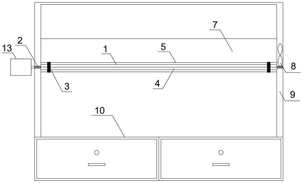
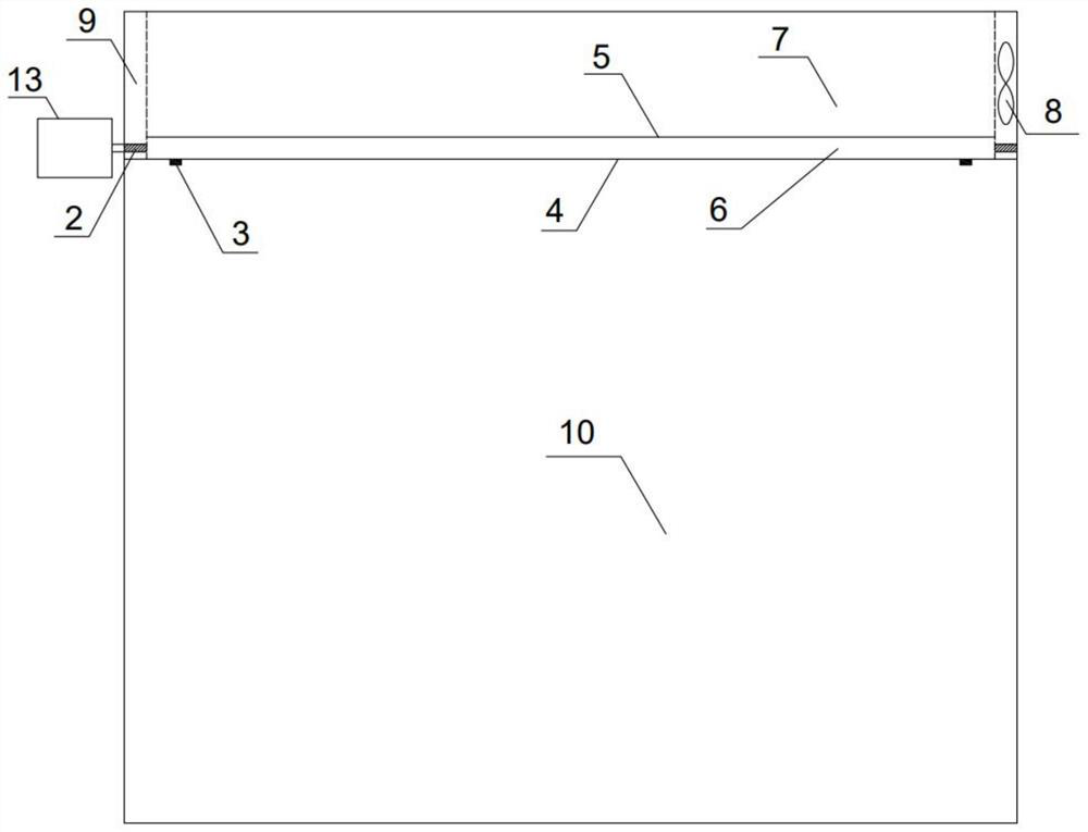
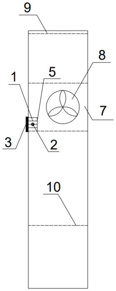
[0037] like Figure 1-Figure 3 As shown, the embodiment of the present invention provides a kind of test bench embedded replaceable local exhaust device, including the test bench reagent rack 9 on the test bench top 10, the test bench reagent rack 9 is provided with an air outlet pipe 7 and a small A local exhaust fan 8 and a local exhaust hood 6 are arranged in the air outlet pipe 7, and the local exhaust hood 6 is connected to the test bench reagent rack 9 through a protruding frame rod 2. Wherein, the air outlet pipe 7 is the cavity in the middle part of the reagent rack 9, and the air outlet pipe 7 is arranged laterally along t...


PUM


Abstract

The invention discloses an experiment table embedded replaceable local exhaust device and exhaust system. The device comprises an experiment table reagent rack arranged on an experiment table top, and an air outlet pipe and a small local exhaust fan are arranged on the experiment table reagent rack; the small local exhaust fan is positioned at an air outlet in the side surface of the experiment table reagent rack; a local exhaust hood is arranged in the air outlet pipe and connected to an experiment table reagent frame through a protruding frame rod, the local exhaust hood is provided with an angle-adjustable louver right opposite to the experiment table top, the angle-adjustable louver is connected with an external connecting rod to achieve vertical overturning, or the outer side of the protruding frame rod is connected with a control motor. And the angle-adjustable louver is driven to turn up and down. The small local exhaust fan enables a negative pressure environment to be formed in the air pipe, and the local exhaust hood is adjusted and overturned up and down to directionally suck pollution gas into the air pipe; and therefore, the pollution gas in the campus laboratory can be efficiently and directionally discharged.

Description

technical field [0001] The invention relates to a laboratory local exhaust device, in particular to an embedded replaceable local exhaust device for a test bench. Background technique [0002] The air quality in campus laboratories directly affects the comfort and health of teaching staff. At present, laboratories in primary and secondary schools do not have complete ventilation devices and systems, and directional removal of polluted gases in laboratories is a common problem that needs to be solved urgently. [0003] At present, university laboratories use natural ventilation, exhaust hoods and fume hoods to remove indoor pollutants. Although the way of natural ventilation is relatively economical, its ventilation volume is often difficult to control, and polluting gases cannot be removed in time, which will lead to indoor air quality not meeting the requirements. The way of the exhaust hood is to arrange several air outlets in the laboratory to discharge the polluted gas...

Claims


Application Information

Patent Timeline
Patent Type & Authority Applications(China)
IPC IPC(8): B08B15/02B08B13/00
CPCB08B15/023B08B13/00
Inventor 胡静白晶张璇
Owner XI'AN UNIVERSITY OF ARCHITECTURE AND TECHNOLOGY
Why Eureka
Try Eureka