Power transmission device capable of adjusting supporting direction and angle
A power transmission and adjustable technology, which is applied in the spatial arrangement/configuration of cables, towers, building types, etc., can solve the problems of inability to mass-produce modules, inability to change, and difficulty in controlling the cost of use
- Summary
- Abstract
- Description
- Claims
- Application Information
AI Technical Summary
Problems solved by technology
Method used
Image
Examples
Embodiment 1
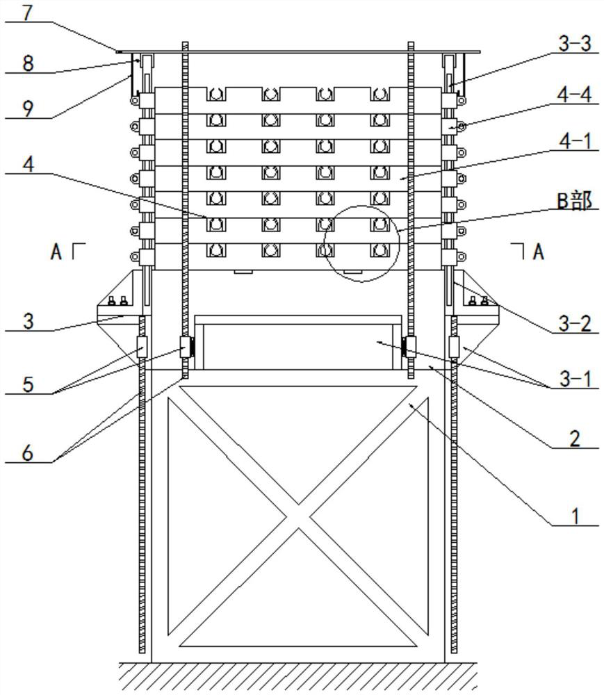
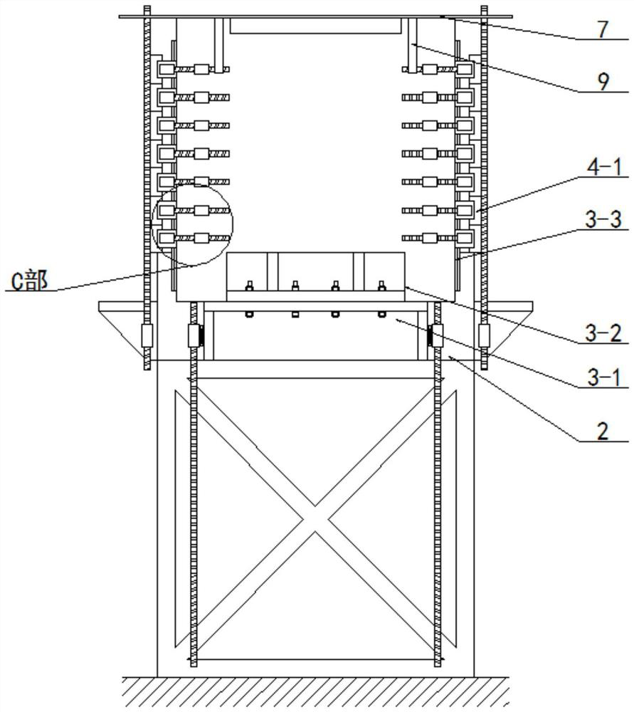
[0040] Such as figure 1 , 2 As shown, this embodiment includes a tower body 1 and a base 2, wherein the tower body 1 is fixed on the foundation by pouring concrete, and the base 2 is fixed on the upper end of the tower body 1 by bolts; it also includes:
[0041] Support 3, the support 3 is two, and symmetrically arranged on the base 2;
[0042] Fixing piece 4, said fixing piece 4 is several, and the front and back are symmetrically arranged in equal quantity, and fixing piece 4 is arranged in cooperation with supporting piece 3;
[0043] Using the above design scheme, when using the device, first install and fix the tower body 1, and then fix the base 2 on the upper end of the tower body 1, and then select the mounting surface of the fixing member 4 according to the direction of the cable, so that the cable can go from The fixing part 4 on one side penetrates, and passes through the fixing part 4 on the other side. At this time, the supporting part 3 is installed and fixed o...
Embodiment 2
[0045] Such as figure 1 , 2 , 4, and 5, on the basis of the above-mentioned embodiment 1, the support 3 includes:
[0046] There are four fixing seats 3-1, and the four fixing seats 3-1 are respectively fixed on the four side walls of the base 2 by bolts;
[0047] Support base 3-2, the support base 3-2 is two, and the left and right sides are symmetrically fixed on the fixed base 3-1 on the left and right sides of the base 2 by bolts, the upper end of the support base 3-2 is higher than the base The upper surface of seat 2 is set;
[0048] Slide rail 3-3, described slide rail 3-3 is four, and on the front and rear sides of the support base 3-2 on left and right sides symmetrically fixed on the front and back by two by two groups, on the front and back sides of slide rail 3-3 The lower end is set lower than the upper surface of the base 2;
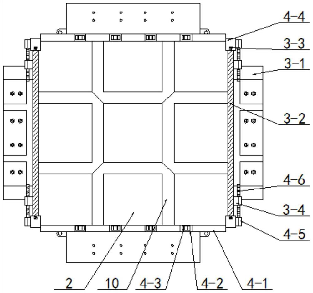
[0049] Supporting threaded sleeve 3-4, said supporting threaded sleeve 3-4 is several, and front and back are arranged symmetrically, ...
Embodiment 3
[0052] Such as figure 1 , 2 , 4, and 5, on the basis of the above-mentioned embodiment 2, the fixing member 4 includes:
[0053] Limiting seat 4-1, the number of limiting seats 4-1 is several, and the front and rear are symmetrically arranged, and the upper side of the limiting seat 4-1 is equidistantly opened with several limiting grooves 4 from left to right -2;
[0054] The clamp 4-3, the clamp 4-3 is set in the limit groove 4-2, and the clamp 4-3 is fixed on the limit seat 4-1 by bolts;
[0055] Slider 4-4, said slider 4-4 is symmetrically fixed on the left and right ends of the limit seat 4-1 by bolts, and the slider 4-4 is slidably arranged on the corresponding slide rail 3-3;
[0056] The limit sleeve 4-5, the limit sleeve 4-5 is fixed on the slide block 4-4 by bolts, and the limit sleeve 4-5 and the supporting threaded sleeve 3-4 are set in one-to-one correspondence;
[0057] Supporting threaded rod 4-6, said supporting threaded rod 4-6 is threaded and inserted in su...
PUM
 Abstract
Description
Claims
Application Information
 - R&D Engineer
- R&D Manager
- IP Professional
- Industry Leading Data Capabilities
- Powerful AI technology
- Patent DNA Extraction
Browse by: Latest US Patents, China's latest patents, Technical Efficacy Thesaurus, Application Domain, Technology Topic, Popular Technical Reports.
© 2024 PatSnap. All rights reserved.Legal|Privacy policy|Modern Slavery Act Transparency Statement|Sitemap|About US| Contact US: help@patsnap.com


