PVC corrugated pipe cutting equipment
A technology of cutting equipment and bellows, applied in the field of pvc bellows cutting equipment, can solve the problems of poor health of operators, substandard quality of cut products, and inability to use normally, so as to reduce manpower consumption, improve cutting quality, and facilitate The effect of feeding
- Summary
- Abstract
- Description
- Claims
- Application Information
AI Technical Summary
Problems solved by technology
Method used
Image

Examples
Embodiment 1
[0032] A pvc corrugated pipe cutting equipment such as Figure 1-14 As shown, it includes a first support frame 1, a second support frame 101, a third support frame 102, a slide rail 104, a cutting mechanism, a clamping mechanism, an automatic discharging mechanism and an automatic feeding mechanism, and the first support frame 1 is located at At the front of the equipment, the bellows passes through the middle of the first support frame 1. Two slide rails 104 are fixed on the bottom of the rear wall of the first support frame 1. The rear part of the top wall of each slide rail 104 is provided with a plurality of threaded holes. A third support frame 102 is fixed on the rear part of the top wall of the two slide rails 104, and the third support frame 102 is used to install the cutting mechanism, and a second support frame is fixed on the front position of the middle part of the right wall of the slide rail 104 on the right side 101, the cutting mechanism is installed in the th...
Embodiment 2
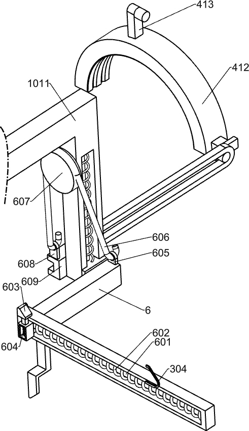
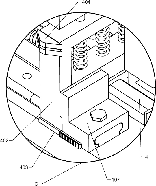
[0035] On the basis of Example 1, such as figure 2 , Figure 4-5 and Figure 8 As shown, the automatic feeding mechanism includes a first slideway 1001, No. 4 motor 4, a second screw mandrel 401, a first sliding frame 402, a first fixed column 405, a second sliding frame 406, a first sliding rod 407, The first spring 408, the first sliding inclined block 409, the second spring 410, the second connecting frame 411, the sliding clip 412, the L-shaped bar 413 and the fixed slideway 414, the rear wall right side of the first support frame 1 is fixed with A first slideway 1001, a No. 4 motor 4 is installed in the middle of the rear side of the top wall of the two slide rails 104, and a second screw 401 is connected to the output shaft of the No. 4 motor 4. The No. 4 motor 4 drives the second wire The rod 401 rotates, and the front end of the second screw mandrel 401 is connected to the bottom of the rear wall of the first support frame 1, and a first sliding frame 402 is jointly...
Embodiment 3
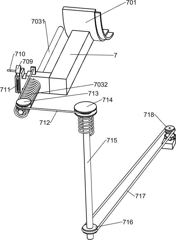
[0046] On the basis of Example 2, such as figure 1 and Figure 14 As shown, it also includes connecting shaft 103, feeding guide plate 5, connecting block 501, second connecting rod 502, third sliding rod 503, hook 504, second fixing column 505, torsion spring 506 and the third fixing block 507 , the middle part of the front side of the first support frame 1 is fixed with a connecting shaft 103, a connecting block 501 is rotatably connected to the connecting shaft 103, a feeding guide plate 5 is fixedly connected to the top of the connecting block 501, and the top of the feeding guide plate 5 It is a semicircular track, and the position where the front wall of the feed guide plate 5 contacts the track is an arc surface, and the bottom of the first support frame 1 is slidably connected with a third slide bar 503, and the feed guide plate 5 A second connecting rod 502 is rotatably connected to the front side of the bottom of the bottom, and the second connecting rod 502 plays a...
PUM
 Abstract
Description
Claims
Application Information
 - Generate Ideas
- Intellectual Property
- Life Sciences
- Materials
- Tech Scout
- Unparalleled Data Quality
- Higher Quality Content
- 60% Fewer Hallucinations
Browse by: Latest US Patents, China's latest patents, Technical Efficacy Thesaurus, Application Domain, Technology Topic, Popular Technical Reports.
© 2025 PatSnap. All rights reserved.Legal|Privacy policy|Modern Slavery Act Transparency Statement|Sitemap|About US| Contact US: help@patsnap.com