Robot quick-change tool magazine
A tool library and robot technology, applied in the direction of manufacturing tools, tool storage devices, manipulators, etc., can solve the problems of tools smashing workers, time-consuming and laborious, poor executable, etc., and achieve the effect of safe grasping tools
- Summary
- Abstract
- Description
- Claims
- Application Information
AI Technical Summary
Problems solved by technology
Method used
Image
Examples
Embodiment 1
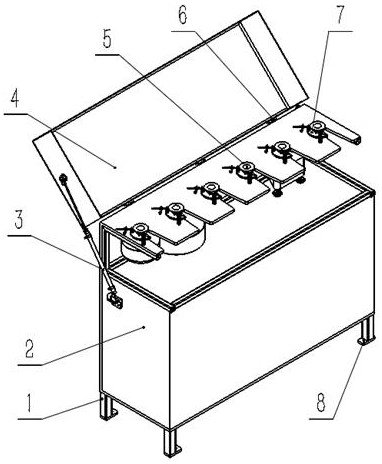
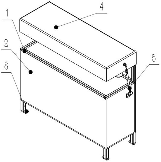
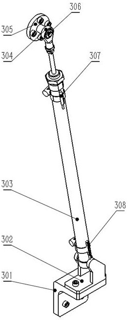
[0030] Such as Figure 1-4 As shown, a robot quick-change tool library includes a box body 1, the bottom of the box body 1 is provided with feet 8, the outside of the box body is covered by a cover, the upper part of the box body 1 is provided with a tool mounting table, and the tool mounting table is There are several tool placement positions 5 for processing; a tool 7 is placed in each tool placement position 5;
[0031] The tool placement position 5 is a U-shaped notch with a large mouth and a small bottom. One side edge of the U-shaped notch is provided with a crescent-shaped plate 706. One side edge of the crescent-shaped plate 706 is concave, and the concave surface of the crescent-shaped plate 706 faces the tool. Placement position 5, the crescent-shaped plate 706 has a rotating shaft 705, and the lower end of the rotating shaft 705 is installed on the tool installation table; the crescent-shaped plate 706 does not necessarily have to be crescent-shaped, as long as one ...
Embodiment 2
[0041] Such as Figure 5 As shown, similar to Embodiment 1, the difference is that the first protrusion 9 and the second protrusion 10 are provided on both sides of the lower part of the crescent-shaped plate 706, and the first protrusion is located at a distance from the bottom of the U-shaped notch. On the side, the second protrusion is located on the side close to the bottom of the U-shaped notch.
[0042] The tool placement position 5 on the side of the crescent-shaped plate 706 is provided with a first arc-shaped groove 11 and a second arc-shaped groove 12 centered on the rotating shaft 705; the first arc-shaped groove 11 is located away from the bottom of the U-shaped notch On one side, the second arc-shaped groove 12 is arranged on the side close to the bottom of the U-shaped notch; the first arc-shaped groove 11 is adapted to the first protrusion, and the second arc-shaped groove 12 is adapted to the second protrusion;
[0043] A first sensor 13 is provided at the bot...
Embodiment 3
[0047] Such as Figure 6 As shown, similar to Embodiment 1, the difference is that the tool placement position 5 on the side of the crescent-shaped plate 706 is provided with a third arc-shaped groove 15 with the rotating shaft 705 as the center of the circle, and the third arc-shaped groove 15 middle part is provided with switch 16, judges that tool 7 is in out of storage or storage state by switch being in open or closed state, first projection 9 and second projection 10 are arranged in the 3rd arc groove 15, and switch 16 is set Between the first protrusion 9 and the second protrusion 10 .
[0048] When the tool 7 is put into the warehouse, the crescent-shaped plate 706 rotates, and the second protrusion approaches the switch. When the tool 7 is put into the warehouse, the second protrusion contacts the switch, forcing the switch 16 to change state and send a warehouse-in completion signal; the tool 7 When going out of the warehouse, the crescent-shaped plate 706 rotates, ...
PUM
 Abstract
Description
Claims
Application Information
 - R&D
- Intellectual Property
- Life Sciences
- Materials
- Tech Scout
- Unparalleled Data Quality
- Higher Quality Content
- 60% Fewer Hallucinations
Browse by: Latest US Patents, China's latest patents, Technical Efficacy Thesaurus, Application Domain, Technology Topic, Popular Technical Reports.
© 2025 PatSnap. All rights reserved.Legal|Privacy policy|Modern Slavery Act Transparency Statement|Sitemap|About US| Contact US: help@patsnap.com


