Uninterrupted power supply (UPS) device with monitoring function

A technology of power supply equipment and functions, which is applied to the structural parts of electrical equipment, emergency power supply arrangements, electrical components, etc., and can solve problems such as lack of monitoring devices, damage to load equipment, and explosions.

Pending Publication Date: 2022-05-06
深圳市小樱桃实业有限公司
View PDF0 Cites 2 Cited by
  • Summary
  • Abstract
  • Description
  • Claims
  • Application Information

AI Technical Summary

Problems solved by technology

[0003] At present, the existing UPS equipment does not have a special monitoring device. When the UPS is working, the device will play an obvious role after the mains power failure, so most of the time the staff cannot find its fault, but when the power supply After a fault occurs, if it cannot be found and dealt with in time, not only will it lose its ability to supply power in the event of a power outage, but the power supply may also spontaneously ignite or explode, which will damage itself while also Affect the damage of the load equipment receiving power supply

Method used


Image

  • Uninterrupted power supply (UPS) device with monitoring function
  • Uninterrupted power supply (UPS) device with monitoring function
  • Uninterrupted power supply (UPS) device with monitoring function

Examples


Embodiment 1

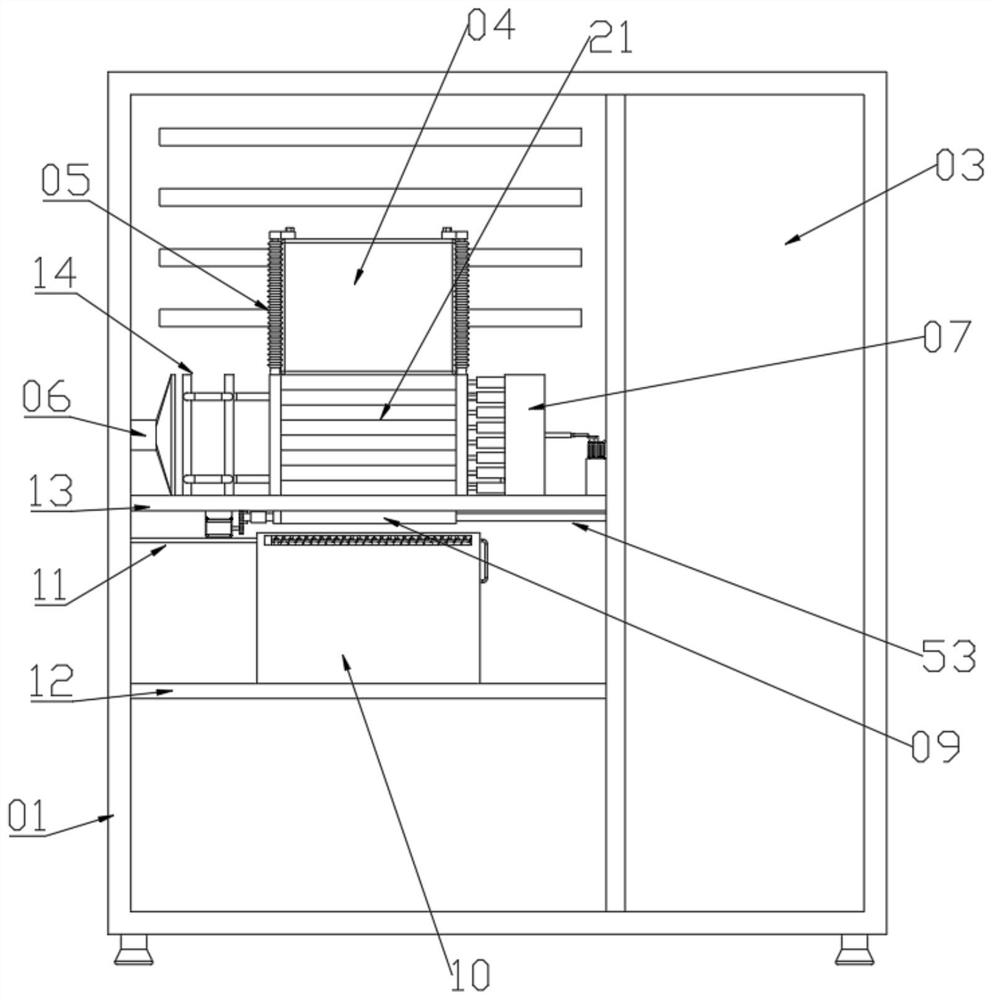
[0035] see Figure 1 to Figure 7 And the closed box 10 shown in Figure 10 to the partition board 12 in Figure 1, a kind of UPS uninterruptible power supply equipment with monitoring function, including the partition board 2 13 installed in the chassis 01, and the partition board 2 13 is fixedly connected with three diversion columns 2 19 And one guide post 18, and three guide posts 19 and guide post 18 form a rectangle, and between each guide post 19 and between guide post 18 and guide post 2 19 Both are provided with heat-absorbing strips 21 and cooling liquid is arranged in the heat-absorbing strips 21, and the heat-absorbing strips 21 are connected with the second guide column 19, but only the heat-absorbing strip 21 on one side is connected with the guide column one 18, and there is no The heat-absorbing bar 21 of one side being communicated with diversion post-18 is communicated with communicating pipe-32, and heat-absorbing bar 21 is the material of softness, and the rec...

Embodiment 2

[0039] see Figure 1 to Figure 7 And the closed box 10 shown in the figure, on the basis of the first embodiment, further, the diversion column one 18 is connected with the connecting pipe two 33, the connecting pipe two 33 is connected with the piston cylinder 27, and the piston cylinder 27 is connected with the piston box 07, A piston plate 36 is slidably connected in the piston box 07, and a piston rod 37 is fixedly connected to the piston plate 36. A one-way valve 35 with a circulation direction facing the inside of the piston cylinder 27 and away from the side of the piston plate 36 is provided on the top. The second guide tube 16 on the piston box 07 is connected with the heat dissipation orifice 14, and the heat dissipation orifice 14 is far away from the One side of the communication position with the diversion tube 2 16 is connected with the diversion tube 1 15, and the end of the diversion tube 15 away from the cooling orifice 14 is connected to the diversion column ...

Embodiment 3

[0043] see Figure 1 to Figure 8 , On the basis of the second embodiment, further, an air inlet plate 17 is provided at the position facing the cooling orifice plate 14 on the second partition plate 13, and the air inlet plate 17 is connected with the air duct 06, and the air duct 06 passes through a The support ring is fixedly connected with a motor one 22, and the output shaft of the motor one 22 is fixedly connected with a fan blade for drawing air outside the chassis 01.

[0044] When the heat dissipation orifice plate 14 quickly volatilizes the heat of the coolant into the air, the motor one 22 will drive the fan blades to rotate, thereby drawing the airflow from the direction of the air inlet plate 17 to the direction of the air cylinder 06, thereby absorbing heat The air quickly discharges from the chassis 01, thereby reducing the temperature in the chassis 01, thereby ensuring the efficiency of heat dissipation.


PUM


Abstract

The invention discloses UPS (Uninterrupted Power Supply) equipment with a monitoring function, which comprises a partition plate II arranged in a case, three diversion columns II and a diversion column I form a rectangle, heat absorption strips are arranged between the diversion columns II and between the diversion columns I and the diversion columns II, and cooling liquid is arranged in the heat absorption strips. The heat absorption strips communicate with the second flow guide column, but only the heat absorption strip on one side communicates with the first flow guide column, a main power source is arranged in a rectangle formed by the second flow guide column and the first flow guide column, a top piece is slidably connected between the two limiting plates in a limiting mode, and the end, away from the heat absorption strips, of a first communicating pipe communicates with a liquid bag. A trigger switch is arranged at the position, away from one side of the liquid bag, of the inner wall of the monitoring strip, a first spring capable of resetting the top piece is arranged in the limiting plate, and a supporting device controlled by the trigger switch is further arranged on the machine box. According to the invention, the function of monitoring the power supply can be realized while the heat dissipation function is realized, and the function of automatically replacing the power supply can also be realized.

Description

technical field [0001] The invention relates to the technical field of power supply equipment, in particular to a UPS uninterruptible power supply equipment with a monitoring function. Background technique [0002] UPS (Uninterruptible Power Supply) is an uninterruptible power supply, which is set up to solve uninterruptible power supply. It connects the battery to the host, and converts the mains power into DC power through a module circuit such as the host inverter. When the mains power fails, it starts to supply power through the power supply. It is mainly used to provide stable and uninterrupted power supply to a single computer, computer network system or other power electronic equipment. It has three basic functions of voltage stabilization, filtering and uninterrupted. [0003] At present, the existing UPS equipment does not have a special monitoring device. When the UPS is working, the device will play an obvious role after the mains power failure, so most of the ti...

Claims


Application Information

Patent Timeline
IPC IPC(8): H02J9/06H05K7/20
CPCH02J9/06H05K7/20927H05K7/20909
Inventor 黄鲁细湛瑞深郭威龙
Owner 深圳市小樱桃实业有限公司
Why Eureka
Try Eureka