Moistureproof indoor electric appliance cabinet capable of accelerating ventilation
A technology for indoor appliances and airbags, applied in electrical components, substation/switch layout details, substation/distribution enclosures, etc., which can solve problems such as poor heat dissipation and slow gas flow
- Summary
- Abstract
- Description
- Claims
- Application Information
AI Technical Summary
Problems solved by technology
Method used
Image
Examples
Embodiment 1
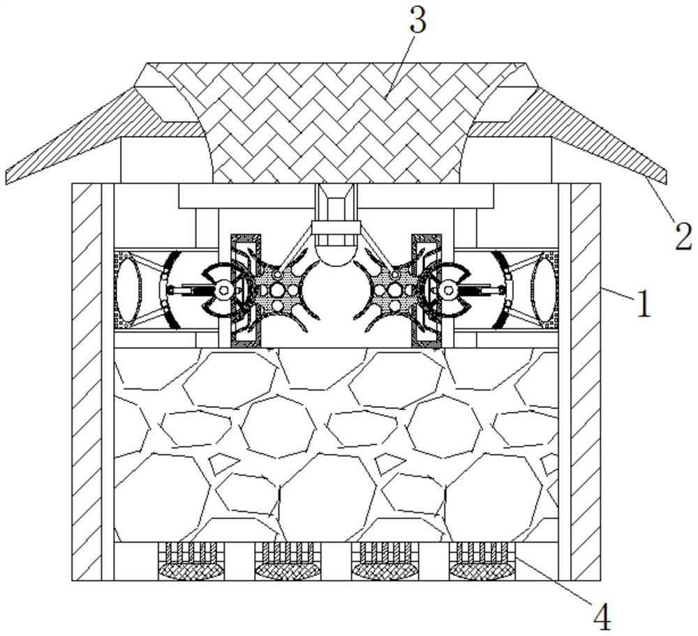
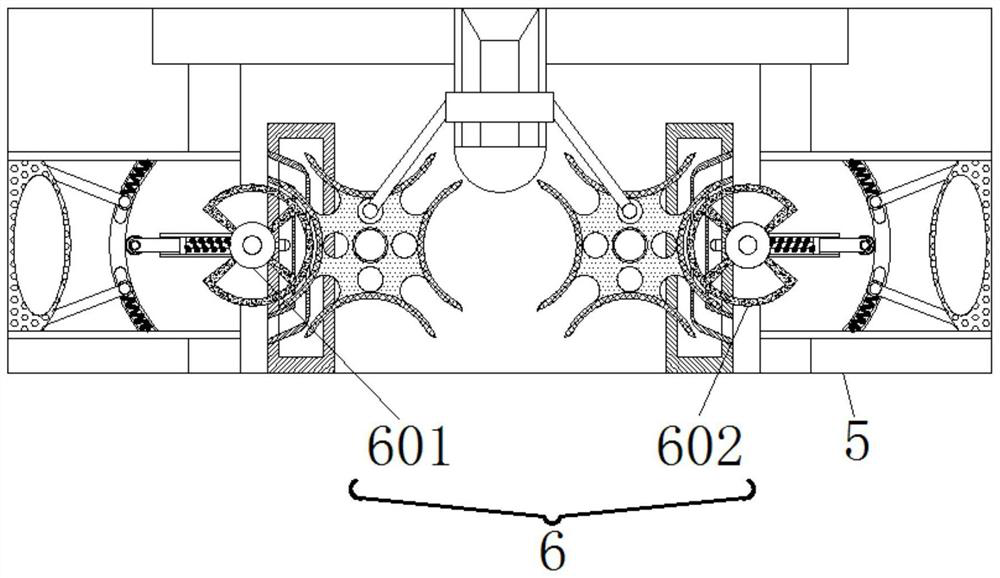
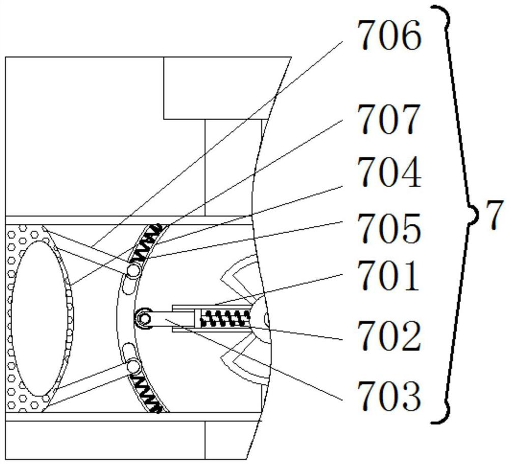
[0027] see Figure 1-3 , a moisture-proof indoor electrical cabinet for accelerating ventilation, comprising a frame 1, a baffle 2 is fixedly installed on the upper end of the frame 1, a ventilation pipe 3 is fixedly installed inside the baffle 2, and a moisture-proof Mechanism 4, the fixed frame 5 is fixedly installed on the upper end of the frame 1 inside, and the left and right ends of the fixed frame 5 are fixedly installed with a symmetrically distributed driving mechanism 6. The driving mechanism 6 includes: a rotating wheel 601, and the outer end of the rotating wheel 601 is fixed. Connecting wheel 602 is installed, drives connecting wheel 602 to rotate by rotating wheel 601, and connecting wheel 602 can drive rotating rod 701 to rotate, and on the relative back side of driving mechanism 6, deflation mechanism 7 is fixedly installed, and deflation mechanism 7 comprises: rotating rod 701 , the inside of the rotating rod 701 is slidably connected with a push rod 703 throu...
Embodiment 2
[0029] see figure 1 , 2 , 4. A moisture-proof indoor electrical cabinet for accelerating ventilation, comprising a frame 1, a baffle 2 is fixedly installed on the upper end of the frame 1, a ventilation pipe 3 is fixedly installed inside the baffle 2, and a bottom end inside the frame 1 is fixedly installed Moisture-proof mechanism 4 is arranged, and the upper end of frame 1 inside is fixedly installed with fixed frame 5, and the left and right ends of fixed frame 5 inside all are fixedly installed with the driving mechanism 6 of symmetrical distribution, and driving mechanism 6 comprises: rotating wheel 601, the outer of rotating wheel 601 The connecting wheel 602 is fixedly installed at the end, and the connecting wheel 602 is driven to rotate by the rotating wheel 601. The connecting wheel 602 can drive the rotating rod 701 to rotate. Suction mechanism 8 is fixedly installed, and suction mechanism 8 comprises: fixed plate 801, and the inside of fixed plate 801 is provided ...
Embodiment 3
[0031] see Figure 1-4, a moisture-proof indoor electrical cabinet for accelerating ventilation, comprising a frame 1, a baffle 2 is fixedly installed on the upper end of the frame 1, a ventilation pipe 3 is fixedly installed inside the baffle 2, and a moisture-proof Mechanism 4, the fixed frame 5 is fixedly installed on the upper end of the frame 1 inside, and the left and right ends of the fixed frame 5 are fixedly installed with a symmetrically distributed driving mechanism 6. The driving mechanism 6 includes: a rotating wheel 601, and the outer end of the rotating wheel 601 is fixed. Connecting wheel 602 is installed, and connecting wheel 602 is an irregular circular design, because connecting wheel 602 is designed irregularly, can drive movable wheel 803 to do intermittent motion, drives connecting wheel 602 to rotate by rotating wheel 601, and connecting wheel 602 can drive Rotating bar 701 rotates, and on the opposite side of driving mechanism 6, deflation mechanism 7 i...
PUM
 Abstract
Description
Claims
Application Information
 - R&D
- Intellectual Property
- Life Sciences
- Materials
- Tech Scout
- Unparalleled Data Quality
- Higher Quality Content
- 60% Fewer Hallucinations
Browse by: Latest US Patents, China's latest patents, Technical Efficacy Thesaurus, Application Domain, Technology Topic, Popular Technical Reports.
© 2025 PatSnap. All rights reserved.Legal|Privacy policy|Modern Slavery Act Transparency Statement|Sitemap|About US| Contact US: help@patsnap.com


