
Method for selecting and evaluating heat dissipation modes of electronic equipment

A technology of electronic equipment and heat dissipation method, which is applied in the field of heat dissipation design of electronic equipment, can solve the problems that cannot be completed, the input of product parameter design is not clear enough, the design data is not detailed enough, etc., and achieve the effect of accurate analysis and easy use

Pending Publication Date: 2022-05-06
XIAN AVIATION COMPUTING TECH RES INST OF AVIATION IND CORP OF CHINA
View PDF0 Cites 0 Cited by
  • Summary
  • Abstract
  • Description
  • Claims
  • Application Information

AI Technical Summary

Problems solved by technology

[0003] At present, the design data that can be used for the selection and evaluation of electronic equipment cooling solutions are not detailed enough, and only roughly explain the allowable power consumption range. The heat dissipation capacity of the outer surface of the chassis cannot be selected and evaluated for specific heat dissipation methods for the structural scheme of electronic equipment
In addition, in the initial stage of product development, the design input of many product parameters is not clear enough, the structure form is not detailed enough, etc., often resulting in the inability to complete the work, and can only rely on the product development experience of the designer to make a rough judgment

Method used


Image

  • Method for selecting and evaluating heat dissipation modes of electronic equipment
  • Method for selecting and evaluating heat dissipation modes of electronic equipment
  • Method for selecting and evaluating heat dissipation modes of electronic equipment

Examples


Embodiment Construction

[0021] Embodiments of the present application will be described in detail below in conjunction with the accompanying drawings.

[0022] Embodiments of the present application are described below through specific examples, and those skilled in the art can easily understand other advantages and effects of the present application from the content disclosed in this specification. Apparently, the described embodiments are only some of the embodiments of this application, not all of them. The present application can also be implemented or applied through other different specific implementation modes, and various modifications or changes can be made to the details in this specification based on different viewpoints and applications without departing from the spirit of the present application. It should be noted that, in the case of no conflict, the following embodiments and features in the embodiments can be combined with each other. Based on the embodiments in this application, all...


PUM


Abstract

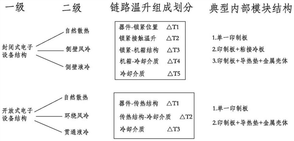
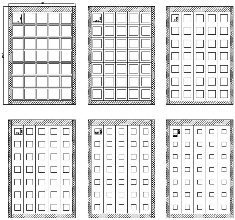
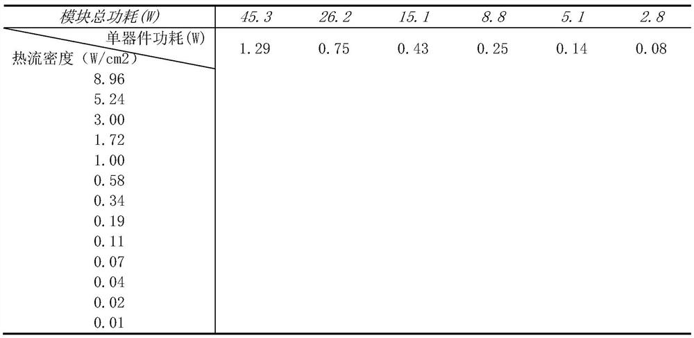
The invention provides a method for selecting and evaluating a heat dissipation mode of electronic equipment, and belongs to the technical field of heat dissipation design of the electronic equipment, and the method specifically comprises the following steps: dividing a two-stage heat dissipation mode architecture, dividing a typical internal module structure and dividing link temperature rise composition; establishing a heat dissipation data framework according to the device size and the device power consumption which are in matrix distribution and equal proportion change, forming a uniform heat dissipation database model which takes the total power consumption of the module and the heat flux density of the device as independent variables and takes the temperature rise of the device as a dependent variable, and obtaining a heat dissipation database of each link; designing the structure of the to-be-tested electronic equipment, and determining a link composition corresponding to the current electronic equipment structure; according to the link composition in the step 3, temperature values of all the compositions are obtained in combination with the database and then added, and the temperature of the current electronic equipment device is obtained. Through the processing scheme provided by the invention, the heat dissipation scheme design of the electronic equipment can be accurately completed at the initial stage of product development.

Description

technical field [0001] The present application relates to the field of heat dissipation design of electronic equipment, in particular to a method for selecting and evaluating heat dissipation methods of electronic equipment. Background technique [0002] In the early stage of the development of electronic equipment, it is often necessary to select and evaluate the heat dissipation scheme of the electronic equipment based on the application environment of the product and the structural design requirements of the product. [0003] At present, the design data that can be used for the selection and evaluation of electronic equipment cooling solutions are not detailed enough, and only roughly explain the allowable power consumption range. The heat dissipation capacity of the outer surface of the chassis cannot be selected and evaluated for specific heat dissipation methods for the structural scheme of electronic equipment. In addition, in the initial stage of product development...

Claims


Application Information

Patent Timeline
Patent Type & Authority Applications(China)
IPC IPC(8): G06F30/20G06F30/10G06F16/21
CPCG06F30/20G06F30/10G06F16/212
Inventor 赵亮董进喜杨明明张丰华张娅妮焦超锋
Owner XIAN AVIATION COMPUTING TECH RES INST OF AVIATION IND CORP OF CHINA
Learn More