
Bearing lubricating device and method

A bearing lubrication and lubricating device technology, applied in the direction of shafts and bearings, bearing cooling, bearing components, etc., can solve the problems of long oil supply time, waste of lubricating oil, uneven oil distribution, etc., to improve the utilization rate of lubricating oil, The effect of shortening the time and speeding up the oil delivery speed

Active Publication Date: 2022-05-06
CENT SOUTH UNIV
View PDF5 Cites 0 Cited by
  • Summary
  • Abstract
  • Description
  • Claims
  • Application Information

AI Technical Summary

Problems solved by technology

Due to the high rotational speed of the bearing, the penetration of the lubricating oil is low under the action of wind resistance and centrifugal force in the traditional oil injection lubrication, which is not good for the lubrication effect of the bearing.
[0003] There are some deficiencies in the current bearing lubrication device, such as more waste of lubricating oil, longer oil supply time, uneven oil distribution, etc.

Method used


Image

  • Bearing lubricating device and method
  • Bearing lubricating device and method
  • Bearing lubricating device and method

Examples


Embodiment Construction

[0028] The following will clearly and completely describe the technical solutions in the embodiments of the present invention with reference to the accompanying drawings in the embodiments of the present invention. Obviously, the described embodiments are only part of the embodiments of the present invention, not all of them. Based on the embodiments of the present invention, all other embodiments obtained by persons of ordinary skill in the art without creative efforts fall within the protection scope of the present invention.

[0029] In addition, the technical solutions of the various embodiments of the present invention can be combined with each other, but it must be based on the realization of those skilled in the art. When the combination of technical solutions is contradictory or cannot be realized, it should be considered as a combination of technical solutions. Does not exist, nor is it within the scope of protection required by the present invention.

[0030] Such as...


PUM


Abstract

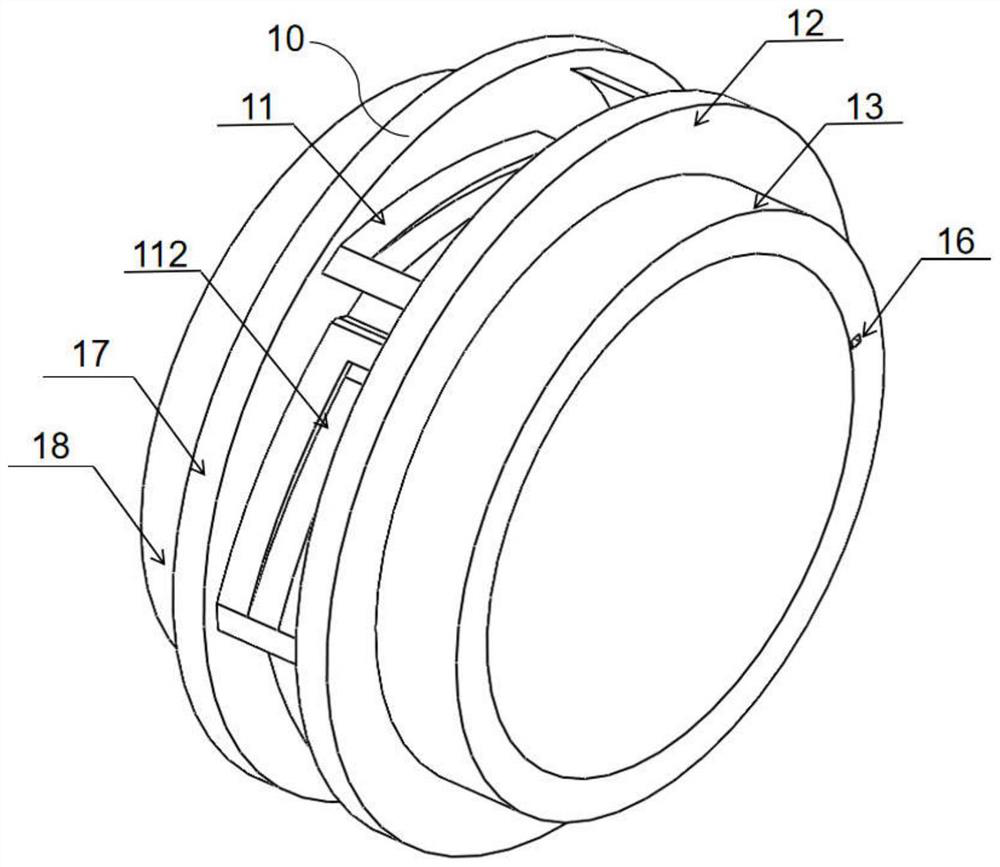
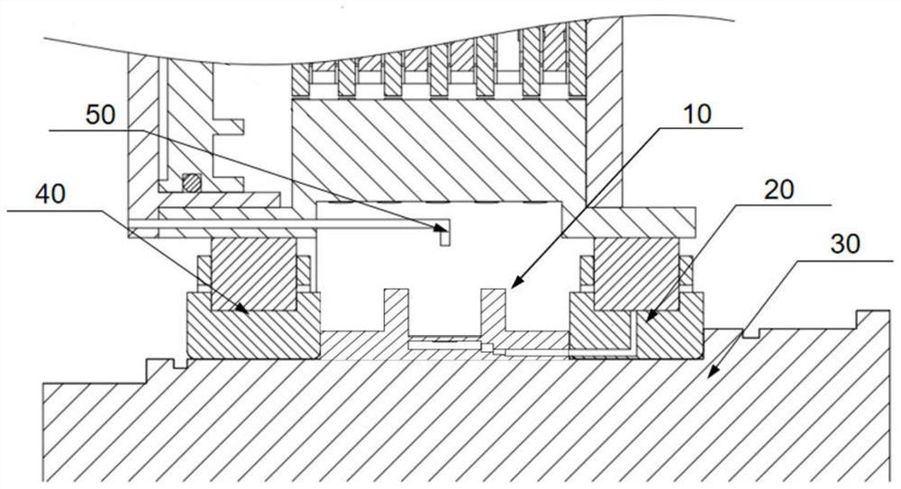
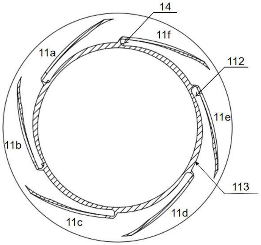
The bearing lubricating device comprises a lubricating device body arranged between a left side bearing and a right side bearing, and the lubricating device body comprises a left side oil retaining wall, a right side oil retaining wall, a left side inner ring, a right side inner ring, a connecting inner ring and an oil collecting spoon. A plurality of oil collecting spoons which are symmetrically distributed by taking the central axis of the connecting inner ring as the center are uniformly distributed on the connecting inner ring and in the lubricating oil groove, the tail end of the oil collecting ring groove is connected with the oil supply groove, the flow speed of lubricating oil in the oil conveying channel is higher under the action of inertia force and gravity, the backflow problem is effectively reduced, and the oil collecting spoons are prevented from falling off under the action of the inertia force. When the bearing rotates, lubricating oil is concentrated at the tail ends of the left and right oil collecting ring grooves and flows into oil conveying channels on the left and right bearing inner rings through the left and right oil supply grooves respectively, and the lubricating oil is thrown into a bearing cavity under the action of centrifugal force generated by high-speed rotation, so that the bearing inner rings on the two sides, a retainer and a roller are lubricated and cooled, and the stable work of the bearing is ensured.

Description

technical field [0001] The invention relates to a bearing lubricating device and method. Background technique [0002] Bearings provide important support for shafts and other rotating parts during the transmission process. The bearings in the reducer are under high-speed and heavy-load conditions, and the working conditions are complicated. During the operation, the friction between the components generates a lot of heat, which causes the inner parts of the bearing components to The temperature rises sharply, which in turn leads to bearing failure and damage. In order to prolong the service life of the bearing, the high-speed rolling bearing must be properly lubricated and cooled. Due to the high rotational speed of the bearing, the penetrability of the lubricating oil is low under the action of wind resistance and centrifugal force in the traditional oil injection lubrication, which is unfavorable to the lubrication effect of the bearing. [0003] There are certain defici...

Claims


Application Information

Patent Timeline
IPC IPC(8): F16C33/58F16C33/66F16C37/00
CPCF16C33/583F16C33/6659F16C37/007
Inventor 胡小舟王佳凝
Owner CENT SOUTH UNIV
Learn More