Vehicle thermal management system and vehicle

A thermal management system and vehicle technology, applied in the field of vehicle thermal management systems, can solve problems such as unreasonable heat collection planning, power loss, energy waste, etc., and achieve the effect of reasonable heat collection planning and avoiding energy waste

Pending Publication Date: 2022-05-06
MIND ELECTRONICS APPLIANCE CO LTD
View PDF0 Cites 0 Cited by
  • Summary
  • Abstract
  • Description
  • Claims
  • Application Information

AI Technical Summary

Problems solved by technology

[0002] For the vehicle thermal management system of a hybrid vehicle, when the hybrid vehicle is driven by the engine, the engine will generate heat. In order to ensure the normal operation of the engine, it is necessary to dissipate heat and cool the engine. demand, the air conditioning system needs to be turned on to heat the passenger compartment. On the one hand, when the ambient temperature is low, the heat absorbed by the refrigerant is limited, and the heating capacity of the air conditioning system is poor. On the other hand, heating the passenger compartment through the air conditioning system will It leads to the loss of electric energy. Since hybrid vehicles can also convert the electric energy of the battery pack into mechanical energy to drive the vehicle in some implementation scenarios, the loss of electric energy is not conducive to improving the endurance of the battery pack.
In other words, the heat collection planning of the existing vehicle thermal management system is unreasonable, resulting in waste of energy

Method used


Image

  • Vehicle thermal management system and vehicle
  • Vehicle thermal management system and vehicle
  • Vehicle thermal management system and vehicle

Examples


Embodiment Construction

[0046] Specific embodiments of the present disclosure will be described in detail below in conjunction with the accompanying drawings. It should be understood that the specific embodiments described here are only used to illustrate and explain the present disclosure, and are not intended to limit the present disclosure.

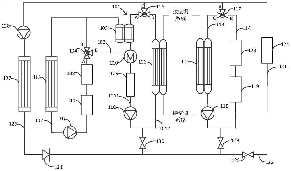
[0047] Such as Figure 1 to Figure 14 As shown, the present disclosure provides a vehicle thermal management system that may be used in a hybrid vehicle. The vehicle thermal management system includes a coolant circuit 101 , a first coolant flow path 102 , a second coolant flow path 103 , a first three-way valve 104 , a first heat exchanger 105 and a second heat exchanger 106 . Wherein, the A port of the first three-way valve 104 is connected with the first end of the first coolant flow path 102, the B port of the first three-way valve 104 is connected with the first end of the second coolant flow path 103, and the first Port C of the three-way valve 104 is...


PUM


Abstract

The invention relates to a vehicle thermal management system and a vehicle. The system comprises a cooling liquid loop, a first cooling liquid flow path, a second cooling liquid flow path, a first three-way valve, a first heat exchanger and a second heat exchanger. A port A of the first three-way valve is connected with the first end of the first cooling liquid flow path, a port B of the first three-way valve is connected with the first end of the second cooling liquid flow path, and a port C of the first three-way valve is connected with the second end of the first cooling liquid flow path and the second end of the second cooling liquid flow path. A first water pump and an engine are arranged on the first cooling liquid flow path, the first heat exchanger is arranged on the second cooling liquid flow path and the cooling liquid loop at the same time, the second heat exchanger is arranged in the cooling liquid loop and an air conditioning system of a vehicle heat management system at the same time, and a warm air core and a second water pump are further arranged on the cooling liquid loop. In this way, heat exchange can be conducted between the engine and the warm air core body, heat exchange can be conducted between the air conditioning system and the warm air core body, and vehicle heat collection planning is reasonable.

Description

technical field [0001] The present disclosure relates to the technical field of vehicle thermal management systems, in particular, to a vehicle thermal management system and a vehicle. Background technique [0002] For the vehicle thermal management system of a hybrid vehicle, when the hybrid vehicle is driven by the engine, the engine will generate heat. In order to ensure the normal operation of the engine, it is necessary to dissipate heat and cool the engine. demand, the air conditioning system needs to be turned on to heat the passenger compartment. On the one hand, when the ambient temperature is low, the heat absorbed by the refrigerant is limited, and the heating capacity of the air conditioning system is poor. On the other hand, heating the passenger compartment through the air conditioning system will It leads to the loss of electric energy. Since the hybrid vehicle can also convert the electric energy of the battery pack into mechanical energy to drive the vehicle...

Claims


Application Information

Patent Timeline
Patent Type & Authority Applications(China)
IPC IPC(8): B60H1/00B60H1/06B60K1/00B60K11/04B60L58/26B60L58/27H01M10/66H01M10/663H01M10/615H01M10/625
CPCB60H1/004B60H1/06B60K1/00B60K11/04B60L58/26B60L58/27H01M10/66H01M10/663H01M10/615H01M10/625B60K2001/005B60K2001/008Y02T10/70
Inventor 尤古塔纳·贝努利
Owner MIND ELECTRONICS APPLIANCE CO LTD
Why Eureka
Try Eureka