Cam device for self-locking tool changing of machining center spindle

A machining center and cam device technology, applied in the field of mechanical processing, can solve the problems of low tool replacement efficiency, low safety, and reduced service life of working motors, and achieve high tool change efficiency, high safety, improved safety, and reasonable structure Effect

Active Publication Date: 2022-05-06
CHANGZHOU UNIV
View PDF7 Cites 0 Cited by
  • Summary
  • Abstract
  • Description
  • Claims
  • Application Information

AI Technical Summary

Problems solved by technology

Therefore, there are still certain disadvantages in the prior art when the tool is replaced: the service life of the working motor is reduced, the tool replacement efficiency is low, and the safety in the tool replacement process is not high.

Method used


Image

  • Cam device for self-locking tool changing of machining center spindle
  • Cam device for self-locking tool changing of machining center spindle

Examples


Embodiment Construction

[0018] The present invention will be further described in detail below in conjunction with the accompanying drawings and specific embodiments.

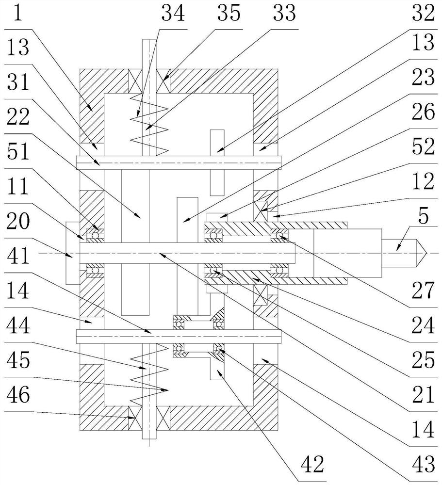
[0019] see figure 1 , a cam device for self-locking tool change of the main shaft of the machining center of the present invention, it includes a cam box 1, a spindle rotation mechanism installed on the cam box 1, and a sliding mechanism installed on the cam box 1 Main shaft locking mechanism and main shaft transmission mechanism. The main shaft rotation mechanism is used to drive the tool 5 to process parts; the main shaft locking mechanism is used to lock the rotation of the tool 5 in a non-stop state for tool replacement; the main shaft transmission mechanism is used to realize the torque transmission of the tool 5 .

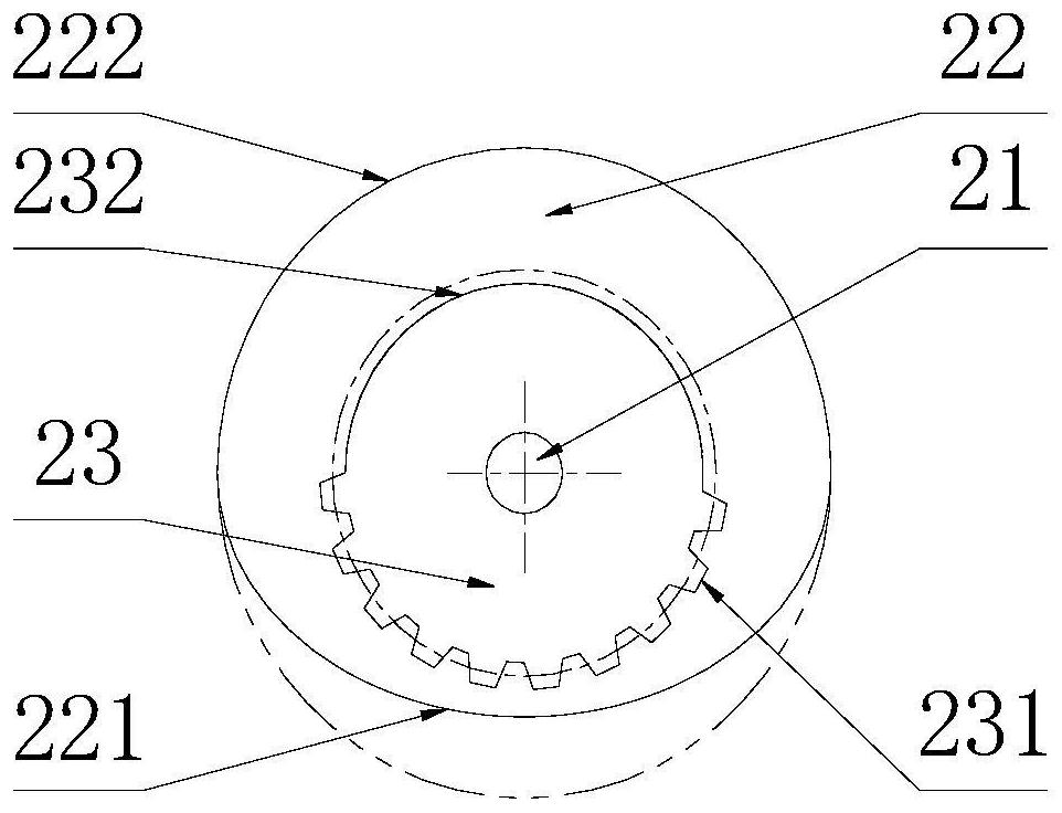
[0020] The left and right side walls of the middle part of the cam box body 1 are respectively provided with a bearing hole A11 for accommodating the main shaft bearing A51 and a bearing hole B12 for accommodating t...


PUM


Abstract

The invention discloses a cam device for self-locking tool changing of a main shaft of a machining center, and belongs to the technical field of machining. The device comprises a cam box body, a main shaft rotating mechanism rotationally arranged on the cam box body, and a main shaft locking mechanism and a main shaft transmission mechanism which are arranged on the cam box body in a sliding manner, the main shaft rotating mechanism comprises an input main shaft, a disc cam, an incomplete gear, an output main shaft, an output gear and a driving motor, the main shaft locking mechanism comprises a sliding locking shaft, a locking gear, a locking guide rod and a tool changing locking spring, and the main shaft transmission mechanism comprises a sliding transmission shaft, a composite idle wheel, a transmission guide rod and a transmission locking spring. The cam device is reasonable in structure, capable of locking the cutter output main shaft without shutdown, efficient in cutter changing, high in safety and suitable for self-locking cutter changing of the machining center.

Description

technical field [0001] The invention mainly relates to the technical field of mechanical processing, in particular to a cam device for self-locking tool change of a spindle of a machining center. Background technique [0002] Machining centers usually need to perform different processing procedures when processing parts, so different tools need to be replaced. In the prior art, the main shaft needs to be stopped for safety when the tool is replaced, that is, the working motor is temporarily stopped and then the tool is replaced; in addition, due to the small static torque of the motor, the tool spindle still has the power of the tool after the motor stops rotating under the action of external force. Possibility of rotation. Therefore, there are still certain disadvantages in the prior art when the cutting tool is replaced: the service life of the working motor is reduced, the cutting tool replacement efficiency is low, and the safety in the cutting tool replacement process ...

Claims


Application Information

Patent Timeline
Patent Type & Authority Applications(China)
IPC IPC(8): B23Q5/20B23Q3/157
CPCB23Q5/20B23Q3/157
Inventor 班书昊李晓艳徐然
Owner CHANGZHOU UNIV
Why Eureka
Try Eureka