Power supply wiring terminal

A power supply wiring and terminal technology, applied in the direction of connection, circuit, electrical components, etc., can solve the problems such as the inability to realize the connection and fixation of the wire and the wiring terminal circuit board, the rust of the fastening bolts, and the looseness. The effect of reducing dust entering the interior of the terminal, reducing wire looseness, and improving wiring efficiency

Pending Publication Date: 2022-04-29
郭颂
View PDF0 Cites 1 Cited by
  • Summary
  • Abstract
  • Description
  • Claims
  • Application Information

AI Technical Summary

Problems solved by technology

[0003] In the installation process of the terminal and the wire in the prior art, a screwdriver is mostly used to turn the internal screw for the connection between the wire and the terminal. However, the screwdriver is often vertical or horizontal when fixing the wire and the circuit board in the terminal. However, this method cannot achieve a good connection and fixation between the wire and the internal circuit board of the terminal block. It is easy to loosen due to the influence of the external environment in the later use process, resulting in poor contact or open circuit. In addition, generally when the wire is connected to the inside of the circuit board, the cable sheath at one end of the wire needs to be peeled off first, and then inserted into the interior of the terminal, and the screwdriver is used to turn the bolt into the interior of the terminal to limit the wire. , this connection method not only requires tools to assist, but also troublesome to install, and at the same time, the fastening bolts used in humid environments are prone to rust and are difficult to fall off, which will affect the subsequent disassembly and maintenance of the wires, and the bolts press the copper wire part of the wires, which is also Easy to cause damage to the wire

Method used


Image

  • Power supply wiring terminal
  • Power supply wiring terminal
  • Power supply wiring terminal

Examples


Embodiment Construction

[0025] The following will clearly and completely describe the technical solutions in the embodiments of the present invention with reference to the accompanying drawings in the embodiments of the present invention. Obviously, the described embodiments are only some, not all, embodiments of the present invention. Based on the embodiments of the present invention, all other embodiments obtained by persons of ordinary skill in the art without making creative efforts belong to the protection scope of the present invention.

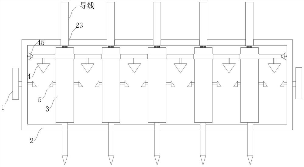
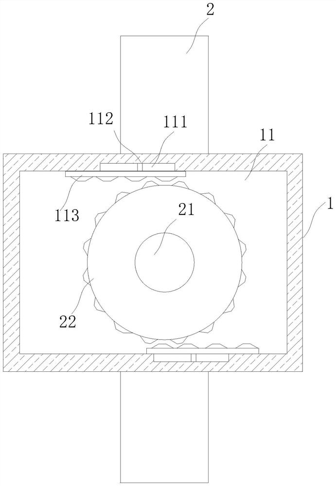
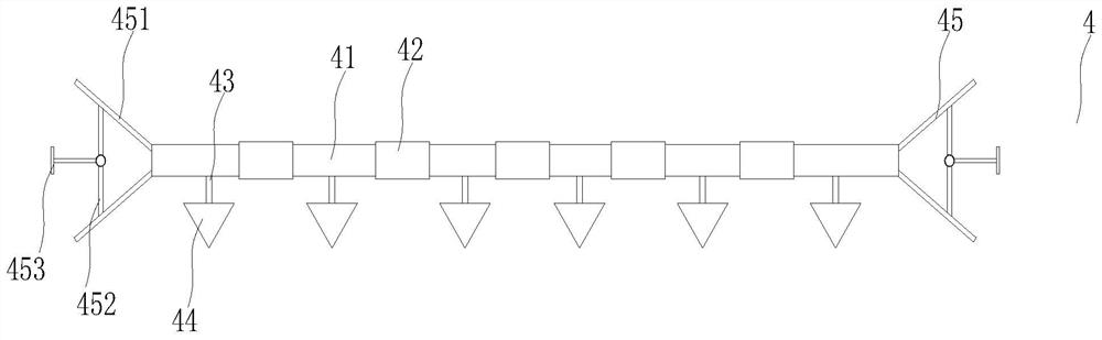
[0026] see Figure 1 to Figure 6 , the present invention provides a technical solution:

[0027] A power terminal, such as figure 1 and figure 2 As shown, it includes a fixed frame 1, the fixed frame 1 is designed in a concave structure, and a junction box 2 is arranged in the middle of the fixed frame 1, and a rectangular groove 11 is opened on the left and right sides of the inner surface of the fixed frame 1, The outer surface of the left and right side...


PUM


Abstract

The invention relates to the technical field of wiring terminals, in particular to a power wiring terminal which comprises a fixing frame, the fixing frame is of a concave structure design, a junction box is arranged in the middle of the interior of the fixing frame, rectangular grooves are formed in the left side and the right side of the inner surface of the fixing frame, and rotating rods are fixedly installed on the outer surfaces of the left side and the right side of the junction box. And a gear is fixedly installed at one end of the rotating rod, the gear is rotationally connected into the rectangular groove, wiring holes are formed in the outer surface of the upper end of the junction box at equal intervals, binding posts are inserted into the junction box at equal intervals, and the binding posts correspond to the wiring holes up and down. According to the invention, the wiring angle can be adjusted according to wiring needs, rapid connection between the binding post and the wire is realized, the wiring efficiency is improved, meanwhile, the complex steps of screwing a screw by using a tool to rotate a fixed joint are reduced, the disassembly and maintenance are convenient, multiple groups of wires are limited at the same time, and the damage to the wire joint is reduced.

Description

technical field [0001] The invention relates to the technical field of connection terminals, in particular to a power supply connection terminal. Background technique [0002] Terminal block is an accessory product used to realize electrical connection. With the development of the electronics industry, the scope of application of terminal blocks is increasing, and there are various types of terminal blocks, such as hardware terminals, nut terminals and spring terminals. Terminals, etc. Terminals are used to facilitate the connection of wires and have great use value. [0003] In the installation process of the terminal and the wire in the prior art, a screwdriver is mostly used to turn the internal screw for the connection between the wire and the terminal. However, the screwdriver is often vertical or horizontal when fixing the wire and the circuit board in the terminal. However, this method cannot achieve a good connection and fixation between the wire and the internal ci...

Claims


Application Information

Patent Timeline
Patent Type & Authority Applications(China)
IPC IPC(8): H01R13/627H01R13/629H01R13/639H01R13/52
CPCH01R13/627H01R13/629H01R13/639H01R13/5219
Inventor 郭颂张志国
Owner 郭颂
Why Eureka
Try Eureka