Path determination method and device

A path determination and target path technology, applied in two-dimensional position/channel control and other directions, which can solve the problems of long time, slow path planning, and large number of target path searches.

Pending Publication Date: 2022-04-29
AGRICULTURAL BANK OF CHINA
View PDF7 Cites 0 Cited by
  • Summary
  • Abstract
  • Description
  • Claims
  • Application Information

AI Technical Summary

Problems solved by technology

[0004] However, the number of searches for the target path obtained by the above process is relatively large, resulting in a long time for path planning and a slow speed of path planning

Method used


Image

  • Path determination method and device
  • Path determination method and device
  • Path determination method and device

Examples


Embodiment Construction

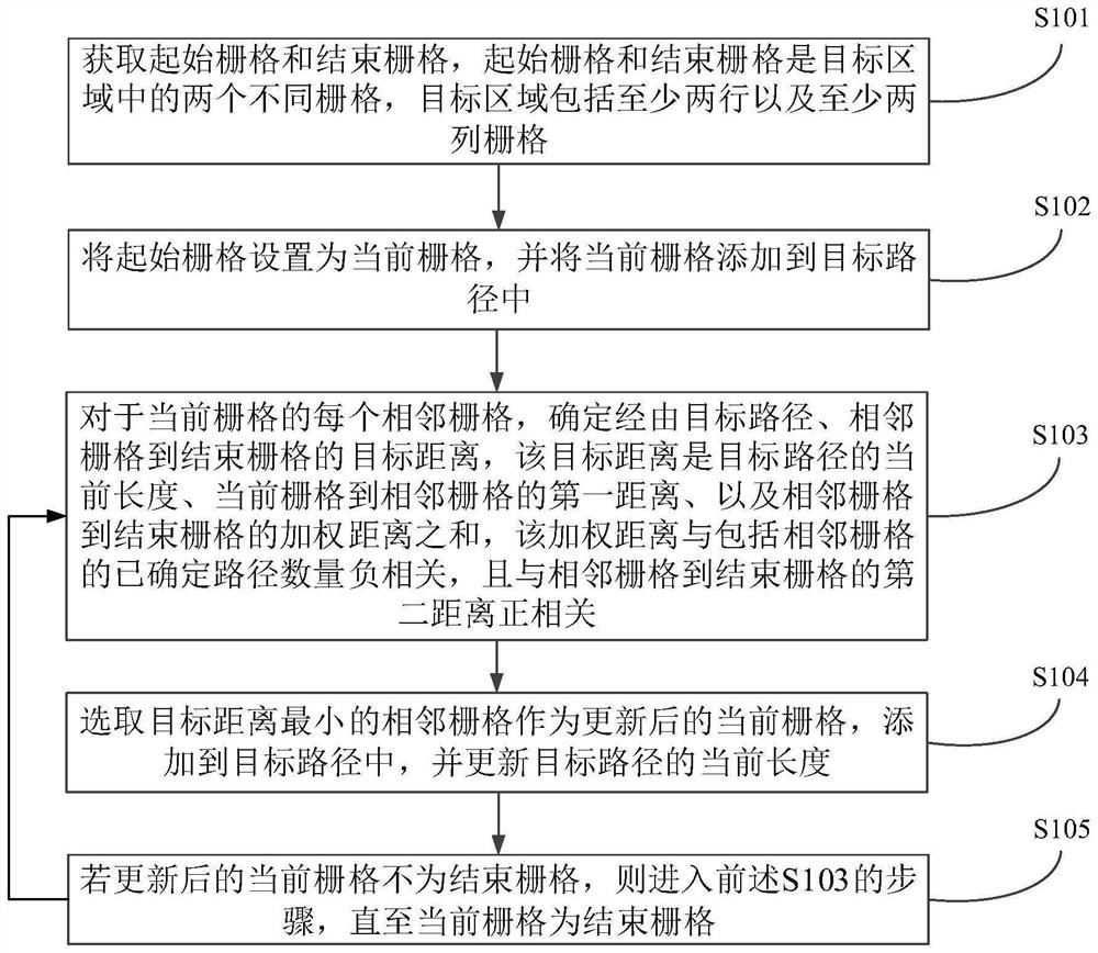
[0031] In order to make the purposes, technical solutions and advantages of the embodiments of the present disclosure clearer, the technical solutions in the embodiments of the present disclosure will be described clearly and completely below with reference to the accompanying drawings in the embodiments of the present disclosure. Obviously, the described embodiments These are some, but not all, embodiments of the present disclosure. Based on the embodiments in the present disclosure, all other embodiments obtained by those of ordinary skill in the art without creative efforts shall fall within the protection scope of the present disclosure.

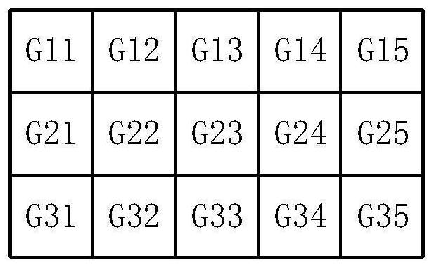
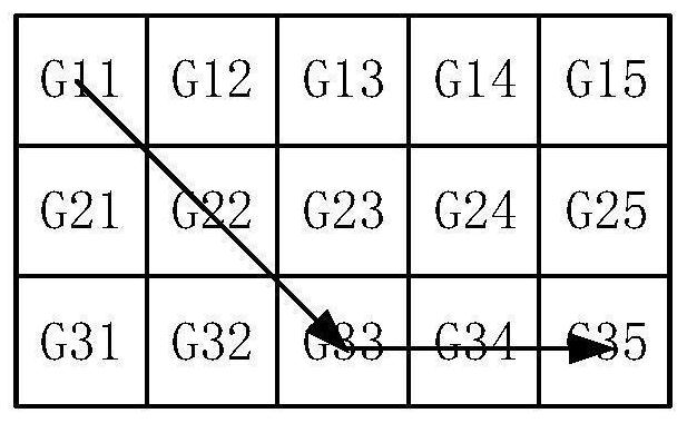
[0032] As described in the background art, the number of searches for determining the target path in the prior art is relatively large, so that path planning takes a long time. According to the research of the inventor, the reason for this problem is that when selecting the next grid to be added to the target path from multiple adjacent ...


PUM


Abstract

The invention provides a path determination method and device, and relates to the technical field of path planning. The method comprises the following steps: setting a starting grid as a current grid to be added into a target path; for each adjacent grid of the current grid, determining a target distance from the adjacent grid to the end grid via the target path, the target distance being a sum of a current length of the target path, a first distance of the current grid to the adjacent grid, and a weighted distance of the adjacent grid to the end grid, the weighted distance is in negative correlation with the number of determined paths including the adjacent grids and is in positive correlation with a second distance from the adjacent grids to the ending grid; selecting an adjacent grid with the minimum target distance as an updated current grid; and if the updated current grid is not the ending grid, entering the step of determining the target distance until the current grid is the ending grid. According to the method, the number of searching times of the grids can be reduced, so that the duration required by path planning is shortened, and the path planning speed is improved.

Description

technical field [0001] The embodiments of the present disclosure relate to the technical field of path planning, and in particular, to a path determination method and device. Background technique [0002] Path planning is used to determine the shortest path from one location (starting location) to another (ending location) in the target area. For example, in an automated warehouse scenario, it is necessary to plan a path for the robot from the current location of the robot to the location of the material, so that the robot can pick up the material, and a target location for the robot to go from the current location of the robot to the place where the material is placed needs to be planned. so that the robot can put the material. For another example, in a navigation scenario, a path from position A to position B needs to be planned for the vehicle. [0003] In the prior art, a target area is divided into M rows and N columns of unit areas, and each unit area is called a gri...

Claims


Application Information

Patent Timeline
Patent Type & Authority Applications(China)
IPC IPC(8): G05D1/02
CPCG05D1/0223G05D2201/0216
Inventor 魏得路
Owner AGRICULTURAL BANK OF CHINA
Why Eureka
Try Eureka