
Electrical element comprehensive test system

A technology for comprehensive testing of electrical components, applied in the direction of circuit breaker testing, etc., can solve problems such as poor compatibility, many testing machines, and low processing performance of DSP chips, so as to ensure work reliability and stability, voltage accuracy and safety performance, to achieve the effect of pull-in release voltage test

Pending Publication Date: 2022-04-29
苏州瑞仪智能科技有限公司
View PDF0 Cites 0 Cited by
  • Summary
  • Abstract
  • Description
  • Claims
  • Application Information

AI Technical Summary

Problems solved by technology

[0002] In order to be able to measure the performance of electrical components, and then to achieve product quality control and provide a test basis for product development, the existing solutions for testing electrical components on the market basically use DSP chips for sampling, but the DSP chip itself processes performance in parallel. It is very low, so it can only be sampled serially and time-sharing, resulting in a single-channel sampling frequency of only about 1KHz, that is, the sampling period is about 1ms, and for the contactor test system, the sampling period of 1ms cannot achieve the key of the contactor at all. Performance testing leads to insufficient measurement accuracy and sampling frequency, and large errors in measurement data
In addition to the above-mentioned problems, the existing test scheme also has the following defects: the waveform cannot be displayed in real time, so that the experimenters cannot judge the cause of the problem, and because there is no isolation safety circuit, it also leads to poor reliability and easy damage, and poor compatibility. It is impossible to realize that one machine can cover the whole series of products of customers, especially the electromagnetic coil control and electromagnet control products of the low-voltage electrical appliance industry, such as contactors, relays, universal circuit breakers, vacuum circuit breakers, etc., which lead to the testing machines invested by customers Many, the test cost is high, and it also affects the test efficiency

Method used


Image

  • Electrical element comprehensive test system
  • Electrical element comprehensive test system

Examples


Embodiment Construction

[0037] The technical solutions of the present invention will be clearly and completely described below in conjunction with the accompanying drawings. Apparently, the described embodiments are some of the embodiments of the present invention, but not all of them. Based on the embodiments of the present invention, all other embodiments obtained by persons of ordinary skill in the art without making creative efforts belong to the protection scope of the present invention.

[0038] In addition, the technical features involved in the different embodiments of the present invention described below may be combined with each other as long as there is no conflict with each other.

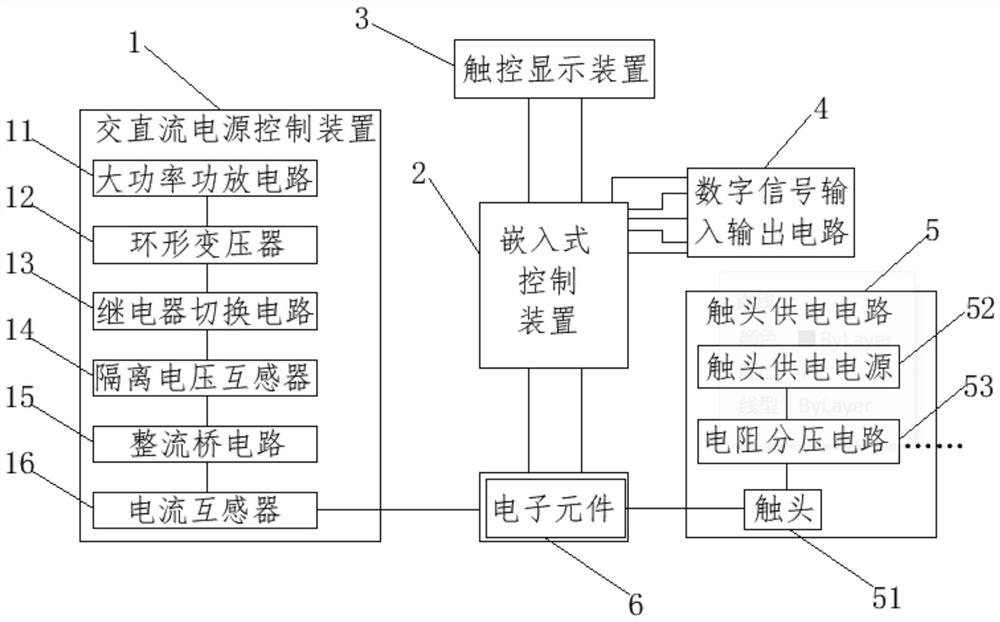
[0039] This embodiment describes a comprehensive testing system for electrical components, such as figure 1 shown, including:

[0040] The AC and DC power supply control device 1 is used to provide multiple operating power supplies with different amplitudes for the loop of the test system;

[0041] The embe...


PUM


Abstract

The invention relates to an electrical element comprehensive test system comprising an AC / DC power supply control device used for providing a plurality of working power supplies with different amplitudes for a loop of the test system; the embedded control device is used for controlling power devices in the AC / DC power supply control device so as to output working power supplies with different amplitudes, acquiring real-time voltages of the multiple ADC channels in real time, processing the real-time voltages, and packaging and sending the real-time voltages; the touch display device is connected with a data serial port of the embedded control device and is used for displaying a test waveform and carrying out man-machine interaction; the digital signal input and output circuit is respectively connected with a data input end and a data output end of the embedded control device; and the contact power supply circuit is electrically connected with the electrical element to be detected and is used for triggering the operation of the electrical element. The device can be suitable for testing different types of coil products in the low-voltage electric appliance industry, the testing precision is high, the working reliability is good, the testing result can be visually displayed, and testers can conveniently judge and trace problems.

Description

technical field [0001] The invention relates to the technical field of testing equipment, in particular to testing equipment in the field of electronics and electricity, and in particular to a comprehensive testing system for electrical components. Background technique [0002] In order to be able to measure the performance of electrical components, and then to achieve product quality control and provide a test basis for product development, the existing solutions for testing electrical components on the market basically use DSP chips for sampling, but the DSP chip itself processes performance in parallel. It is very low, so it can only be sampled serially and time-sharing, resulting in a single-channel sampling frequency of only about 1KHz, that is, the sampling period is about 1ms, and for the contactor test system, the sampling period of 1ms cannot achieve the key of the contactor at all. Performance testing leads to insufficient measurement accuracy and sampling frequenc...

Claims


Application Information

Patent Timeline
IPC IPC(8): G01R31/327
CPCG01R31/327
Inventor 蔡金伟李辉张海牛
Owner 苏州瑞仪智能科技有限公司
Learn More