


Quick Research
Generate reliable direction feasibility study reports for your R&D in just a few steps.

Technical Q&A
Discover and master advanced knowledge NOW. Basics, ideas, possibilities, all at once.

Find Solutions
As an expert in R&D theories, this can generate solutions to your technical problems instantly.

Evaluate Feasibility
Analyze your overall solution with one click, know your potential R&D risks in advance.

Monitor Landscape
Get weekly tech updates, stay abreast of the latest tech innovations and key insights.
Portable clutch discharge device
A technology of discharge device and clutch, applied in the field of clutch, can solve the problems of clean air from clutch, manual discharge, long debugging time, etc., and achieve the effect of improving fluency and quick cleaning
- Summary
- Abstract
- Description
- Claims
- Application Information
AI Technical Summary
Problems solved by technology
Method used
Image


Examples
Embodiment 1
[0026] see figure 1 As shown, the present invention is a portable clutch discharge device, comprising a liquid storage pot 1, a suction pump 2, a power supply 3, a clutch sub-pump 4, an oil pot 5 and a clutch master pump 6; the outlet of the liquid storage pot 1 and the suction pump 2, the output end of the suction pump 2 is connected to the clutch cylinder 4, the clutch cylinder 4 is connected to the oil pot 5, the oil pot 5 is connected to the liquid storage pot 1, and the oil pot 5 and the liquid storage pot 1 are connected. A clutch master cylinder 6 is provided;
[0027] Wherein, the suction pump 2 is electrically connected to the power supply 3, and when the suction pump 2 is working, the power supply 3 supplies the suction pump 2 with electric energy to work;
[0028] The liquid storage pot 1, the suction pump 2, the clutch sub-pump 4 and the oil pot 5 are connected to each other through hoses, and the hoses are 6mm PVC transparent hoses, which have the ability to clea...
Embodiment 2
[0034] A method for assembling a portable clutch discharge device, comprising the following steps:
[0035] Step 1: Use a 12V suction pump 2, and connect 6mm transparent hoses to both ends of the suction pump 2;
[0036] Step 2: The transparent hose on one side is connected to the low liquid level joint of the liquid storage pot 1, and the transparent hose on the other side is connected to the exhaust valve of the clutch cylinder 4;
[0037] Step 3: Connect a section of hose to the high connector of liquid storage pot 1, and connect the hose to the lid 12;
[0038] Step 4: Connect the suction pump 2 to the power supply 3 through electrical connections and switches;
[0039] Step 5: After connecting the pipelines, add a sufficient amount of brake fluid to the reservoir 1;
[0040] Step 6: Turn on the power switch 3, the motor pumps the brake fluid in the reservoir 1 to the clutch cylinder 4, and when the liquid is full, move forward until the pipeline is full;
[0041] Step ...
Embodiment 3
[0043] The liquid storage pot 1 is preferably a container tank that can automatically filter the brake fluid, so that the brake fluid can be filtered each time during the exhaust process, so as to improve the smoothness of the pipeline for a long time;
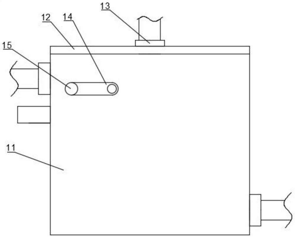
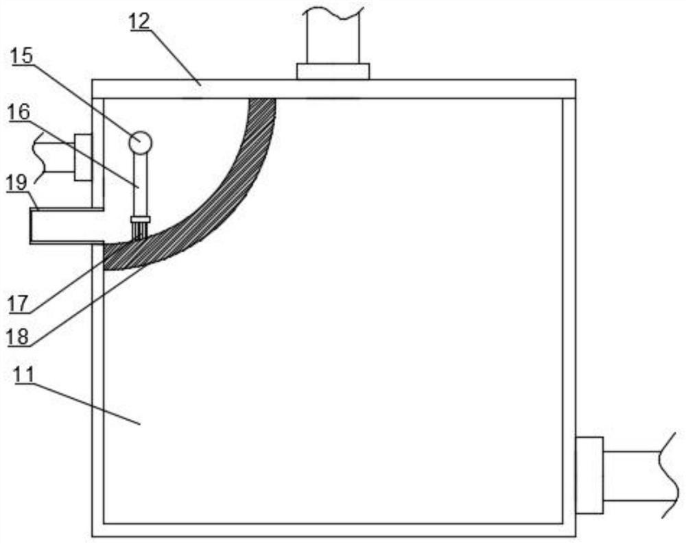
[0044] see figure 2 and image 3 As shown, the liquid storage pot 1 includes a pot body 11, a pot cover 12, a liquid filling port 13, a handle 14, a filter screen 18, and a slag storage box 19; It is convenient to disassemble the pot cover 12 and add brake fluid. A filter screen 18 is arranged above the inner wall of the pot body 11. A filter cavity is formed between the filter screen 18 and the liquid storage pot 1, and a cleaning cavity is arranged in the filter cavity. Gray part, this cleaning part comprises connecting shaft 15, connecting plate 16, hairbrush 17, and connecting shaft 15 runs through filter cavity, and is connected with kettle body 11 rotations, and the outer wall of connecting shaft 15 is provided with co...
PUM
 Abstract
Description
Claims
Application Information
 - R&D Engineer
- R&D Manager
- IP Professional
- Industry Leading Data Capabilities
- Powerful AI technology
- Patent DNA Extraction
Browse by: Latest US Patents, China's latest patents, Technical Efficacy Thesaurus, Application Domain, Technology Topic, Popular Technical Reports.
© 2024 PatSnap. All rights reserved.Legal|Privacy policy|Modern Slavery Act Transparency Statement|Sitemap|About US| Contact US: help@patsnap.com