Underground cast-in-place continuous wall construction method and connecting structure thereof

A cast-in-place continuous wall and construction method technology, which is applied in basic structure engineering, sheet pile walls, buildings, etc., can solve problems such as higher requirements for basic conditions, discontinuous stress transfer, and increased engineering investment, saving engineering investment, It is convenient for continuous transfer and application of obvious effects

Pending Publication Date: 2022-04-29
梁军
View PDF0 Cites 0 Cited by
  • Summary
  • Abstract
  • Description
  • Claims
  • Application Information

AI Technical Summary

Problems solved by technology

[0018] 1. The continuous use of the joint pipe method for the groove section is only suitable for compressive foundations, and it is strictly not allowed for stress environments with tension, twisting, and bending, especially for walls with anti-seepage requirements;
[0019] 2. Concrete or reinforced concrete continuous walls are used for anti-seepage and reinforcement such as earth-rock dams and slopes. Due to the complex stress environment, there is a risk of leakage when using the groove section joint pipe method, and the stress transmission is not continuous;
[0020] 3. Due to the large contact surface of the joint pipe connection, a large mechanical pull-out force is generally required, and large mechanical equipment is required for equipment selection, which is not very economical in practical application
[0021] 4. When the large-scale mechanical extraction equipment is used in the construction of the dam body, the requirements for the dam as a basic condition are relatively high, which virtually increases the project investment and also poses construction safety risks.

Method used


Image

  • Underground cast-in-place continuous wall construction method and connecting structure thereof
  • Underground cast-in-place continuous wall construction method and connecting structure thereof
  • Underground cast-in-place continuous wall construction method and connecting structure thereof

Examples


Embodiment Construction

[0047] The present invention will be further described below with reference to the accompanying drawings and specific embodiments.

[0048] It should be noted that if there are directional indication terms in the present invention, such as up, down, left, right, front, back, direction and orientation terms, they are for the convenience of describing the relative position relationship between components, not for related components and the positions between components. The absolute position of the relationship is specifically used to explain the relative positional relationship, motion, etc. between the various components under a certain posture. If the specific posture changes, the directional indication also changes accordingly. If there are terms related to quantity in the present invention, such as "many", "plurality", "several", etc., it specifically refers to two or more.

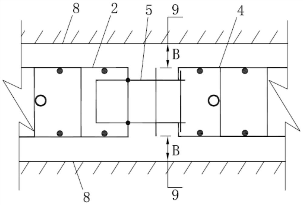
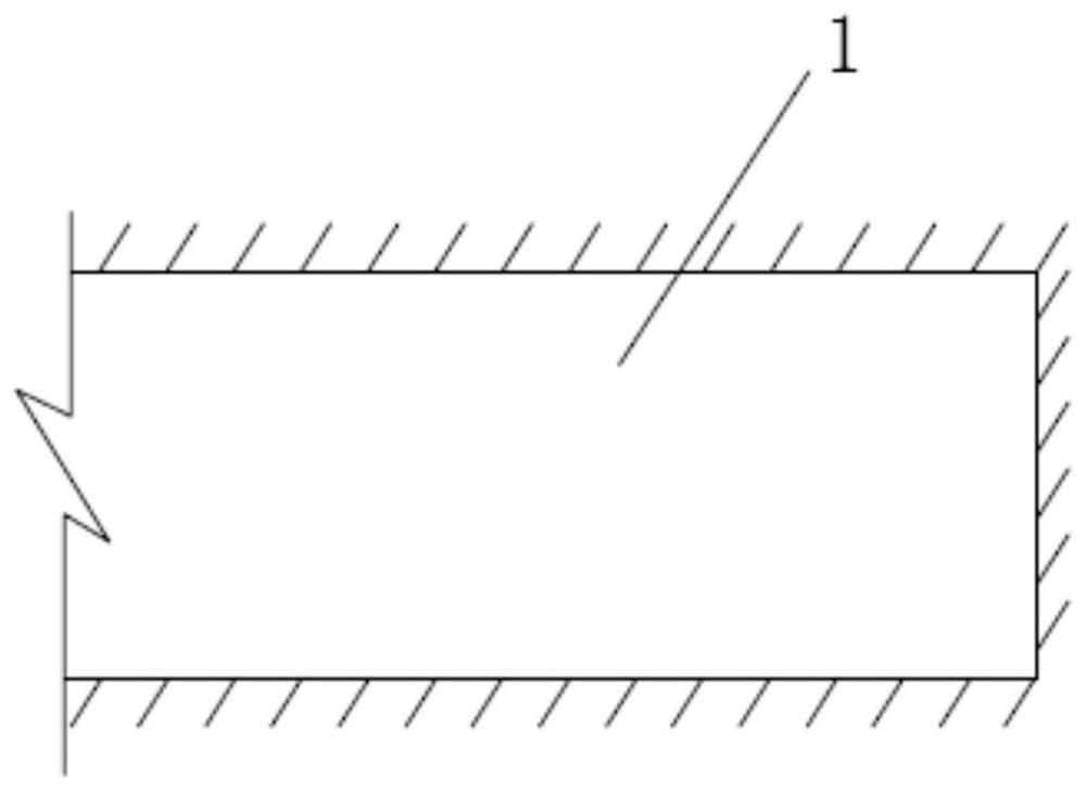
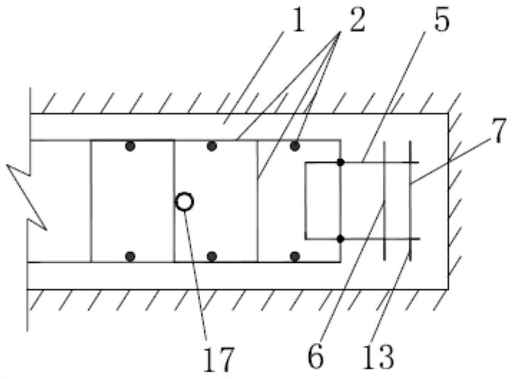
[0049] The underground cast-in-place continuous wall construction method of the present invention co...


PUM


Abstract

The invention discloses an underground cast-in-place continuous wall construction method and a connecting structure thereof, belongs to the technical field of building construction, and provides the underground cast-in-place continuous wall construction method which is continuous in stress and higher in bearing strength and the formed connecting structure. By arranging the corresponding first nesting joint and the second nesting joint and adopting an effective movable buckling connection structure, concrete walls constructed in different hole sequences are connected into an effective whole, and particularly, effective connection between steel trusses in different hole sequences in the construction in different hole sequences is achieved; by means of the structure, continuity of stress in the continuous wall body is guaranteed, continuous transmission of force and deformation is facilitated, the overall performance and the anti-seepage effect of the concrete wall body can be greatly improved, the important guarantee effect is achieved for guaranteeing the quality and safety of the continuous wall body structure, and the practical application effect is quite obvious.

Description

technical field [0001] The invention relates to the technical field of building construction, in particular to an underground cast-in-situ continuous wall construction method and a connection structure thereof. Background technique [0002] The construction of continuous walls using concrete for concealed works began in Italy in the 1940s, and was then effectively applied in the seepage prevention project of the Santan Malin Dam in Italy (a cut-off wall with a depth of 40m). Due to the lag in the research and development of construction equipment, this semi-manual and semi-mechanical excavation and grooving work efficiency is very low and there are safety risks such as collapse and burying. The company developed the world's first hydraulic groove milling machine, which brought the engineering community's attention to this technology again. In the 1990s, the Tokyo Bay Bridge in Japan, Kawasaki artificial island (the wall thickness is 2.8m, the circumference is about 339m), a...

Claims


Application Information

Patent Timeline
Patent Type & Authority Applications(China)
IPC IPC(8): E02D5/18
CPCE02D5/18E02D5/182E02D2220/00E02D2250/0007E02D2300/0029E02D2600/20
Inventor 梁军陈立宝杨燕伟陈昊刘双美向琴徐波
Owner 梁军
Why Eureka
Try Eureka