
Die with swinging and rotating mechanism

A technology of rotating mechanism and moving mold, applied in the field of mold, can solve the problems of long molding cycle, low production efficiency and high cost, and achieve the effects of saving mold opening time, high production efficiency and simple structure

Pending Publication Date: 2022-04-29
苏州润飞精密塑胶科技有限公司 +1
View PDF0 Cites 0 Cited by
  • Summary
  • Abstract
  • Description
  • Claims
  • Application Information

AI Technical Summary

Problems solved by technology

The design of the above mechanism will directly lead to a large mold size and the use of a large-tonnage injection molding machine
Such a mold has the following disadvantages: the structure of the mold is complex and the volume is large, resulting in a large tonnage of the injection molding machine used, a long molding cycle and high cost during production; 540 pieces of products are produced per shift, and the production efficiency is not high

Method used


Image

  • Die with swinging and rotating mechanism
  • Die with swinging and rotating mechanism
  • Die with swinging and rotating mechanism

Examples


Embodiment Construction

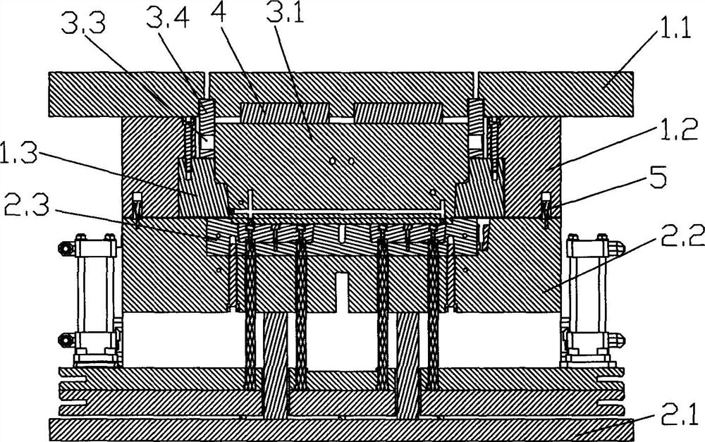
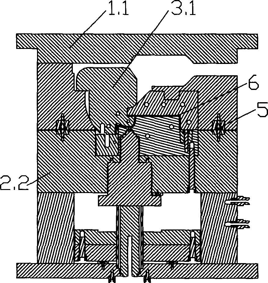
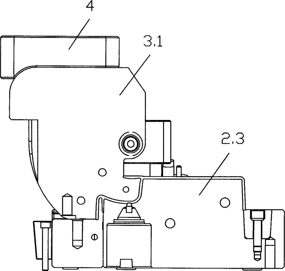
[0016] Referring to Fig. 1-shown in Fig. 4, a kind of mold with swinging and rotating mechanism of the present invention, it comprises fixed mold and movable mold, and fixed mold comprises panel 1.1, fixed mold frame 1.2 and fixed mold kernel 1.3, and described movable mold Including the bottom plate 2.1, the movable mold frame 2.2, the movable mold core 2.3 and the ejection mechanism, the joint surface of the fixed mold core 1.3 and the movable mold core 2.3 forms a product molding cavity, and the fixed mold core 1.3 is equipped with a swinging and rotating mechanism.

[0017] The oscillating and rotating mechanism includes a oscillating core-pulling mechanism 3.1 and a core-pulling block 3.2. The core-pulling block 3.2 is fixed on the lower end of the oscillating core-pulling mechanism 3.1. The oscillating core-pulling mechanism 3.1 is hinged on the fixed mold. A roller 3.3 is provided on the side, and the roller 3.3 rolls and fits in a fixing part 3.4 with a chute, and the f...


PUM


Abstract

The mold comprises a fixed mold and a movable mold, the fixed mold comprises a panel, a fixed mold frame and a fixed mold core, the movable mold comprises a bottom plate, a movable mold frame, a movable mold core and an ejection mechanism, a product forming cavity is formed by the combination surface of the fixed mold core and the movable mold core, and the swing rotating mechanism is arranged in the fixed mold core. The two inserts (the swing core-pulling mechanism and the core-pulling block) for forming the arc-shaped handle and the buckling position of the finished product are combined together and are driven by the panel to swing during demolding, so that the two inserts are separated from the product at one time, and the mold opening time is saved; therefore, the mold is simple in structure, small in size, capable of being formed by a small-tonnage injection molding machine, low in cost and high in production efficiency, and products produced in each shift are improved by more than 1 / 3 compared with the original products.

Description

technical field [0001] The invention belongs to the technical field of moulds, in particular to a mold with an oscillating and rotating mechanism. Background technique [0002] Due to the structure of some products, such as the curved handle on the outer end of the refrigerator pull box, and the buckle (through hole) under the curved handle, the existing mold needs to go through the slider from the buckle first when opening the mold. The core-pulling mechanism that slides out and then separates from the arc-shaped part of the molded product through the rotating mechanism requires two processes to complete. The mold is equipped with two mechanisms (slider mechanism, rotating core-pulling mechanism) to complete the mold opening work successively. The application of this technology is feasible from the perspective of the mold, but from the perspective of enterprise production, it is not in line with its economic benefits and Energy saving and environmental protection require...

Claims


Application Information

Patent Timeline
Patent Type & Authority Applications(China)
IPC IPC(8): B29C45/33B29C45/44
CPCB29C45/332B29C45/44B29C2045/445
Inventor 徐斌贤谢进才
Owner 苏州润飞精密塑胶科技有限公司
Learn More