
Constant-force polishing device

A constant force, grinding seat technology, used in grinding drive devices, grinding/polishing safety devices, grinding/polishing equipment, etc., can solve the problems of increasing distance, easy damage to the manipulator, and the size deviation of the workpiece cannot be too large. , to achieve the effect of reducing the consistency of the workpiece, improving the grinding efficiency and reducing the grinding cost

Pending Publication Date: 2022-04-29
WUXI STIAL TECH
View PDF0 Cites 0 Cited by
  • Summary
  • Abstract
  • Description
  • Claims
  • Application Information

AI Technical Summary

Problems solved by technology

This grinding method has high requirements on the consistency of the workpiece, and the size deviation of the workpiece should not be too large. For example, if the size is too large, the pressure on the manipulator during grinding will be greater, which will easily damage the manipulator. If the size is too small, it will not be polished.
And with the wear of the grinding wheel, the distance between the grinding wheel and the workpiece becomes larger, but the grinding track is set according to a constant grinding distance, which causes the quality of grinding after the grinding wheel is worn to not meet the requirements

Method used


Image

  • Constant-force polishing device
  • Constant-force polishing device
  • Constant-force polishing device

Examples


Embodiment Construction

[0023] The present invention will be further described now in conjunction with accompanying drawing.

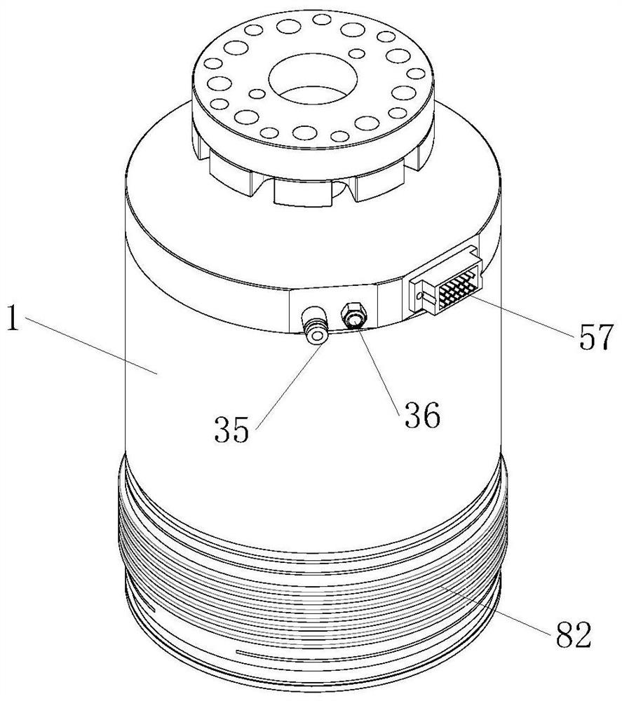
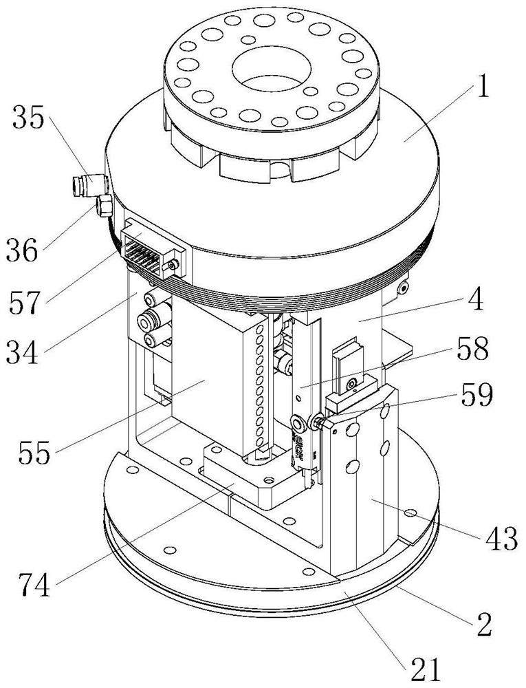
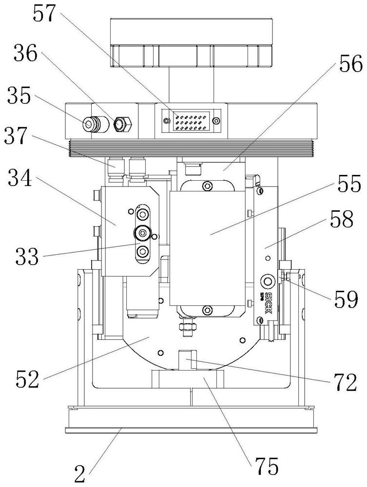
[0024] like Figure 1 to Figure 7 As shown, a constant force grinding device includes a proportional control valve 31, a cylinder 7, a connecting seat 1, a guide bracket 41, a lifting bracket 43, a grinding seat 2, a control panel 51, a protective tube 81 and a telescopic dust cover 82.

[0025] The top of the connection base 1 is equipped with a connection head 10 for connecting with the manipulator. A wiring hole 11 , an air inlet hole 12 and an air outlet hole 13 are provided on the outer surface of the connection base 1 , and the wiring hole 11 , the air inlet hole 12 and the air outlet hole 13 are all communicated with the bottom of the connection base 1 . The first connector 35 and the second connector 37 are respectively installed at two ends of the air inlet 12 . The second joint 37 is connected to the proportional control valve 31 through an air pipe. Multi-core j...


PUM


Abstract

The invention relates to a constant-force polishing device which comprises a proportional control valve, an electromagnetic valve and an air cylinder, the proportional control valve is connected with the air cylinder through the electromagnetic valve, the constant-force polishing device further comprises a connecting base, a guide support, a lifting support, a polishing base, a control panel and a telescopic dust cover, and the guide support, the proportional control valve and the air cylinder are all fixed to the connecting base; the lifting supports are slidably installed on the guide support and located on the two sides of the air cylinder. The grinding seat is fixed on the lifting bracket; the control panel is fixed on the connecting seat or the guide bracket; the control panel is electrically connected with the proportional control valve and the electromagnetic valve; the two ends of the telescopic dust cover are connected with the connecting base and the grinding base correspondingly. According to the constant-force grinding device, the distance between the grinding wheel and the surface of a workpiece can be adjusted in real time, constant-force grinding is achieved, the grinding quality is stable and reliable, the requirement for the consistency of the workpiece is lowered, the grinding efficiency is improved, early-stage preparatory work is reduced, and the grinding cost is reduced.

Description

technical field [0001] The invention relates to a grinding device, in particular to a constant force grinding device. Background technique [0002] In order to improve the grinding efficiency and grinding quality, more and more manipulators are used for grinding. When grinding, the manipulator grinds the workpiece according to the preset grinding trajectory. This grinding method has high requirements on the consistency of the workpiece, and the size deviation of the workpiece should not be too large. For example, if the size is too large, the pressure on the manipulator during grinding will be high, which is easy to damage the manipulator, and the size is too small to be polished. And along with the wearing and tearing of grinding wheel, the distance between grinding wheel and workpiece becomes bigger, but grinding track is set according to constant grinding distance, causes the quality of grinding after grinding wheel wears and does not meet the requirement. Contents of ...

Claims


Application Information

Patent Timeline
Patent Type & Authority Applications(China)
IPC IPC(8): B24B49/16B24B55/06B24B47/06B24B55/00
CPCB24B49/165B24B55/06B24B47/06B24B55/00
Inventor 王红波郑宁夏
Owner WUXI STIAL TECH
Learn More