Four-frequency power divider based on stepped impedance coupling line

A technology of stepped impedance and coupled lines, applied in the field of multi-frequency power divider design, can solve the problems of low isolation, complex design structure, and insufficient miniaturization requirements, and achieve low production cost, simplified structure, and favorable processing integration Effect

Active Publication Date: 2022-04-26
XIDIAN UNIV
View PDF3 Cites 0 Cited by
  • Summary
  • Abstract
  • Description
  • Claims
  • Application Information

AI Technical Summary

Problems solved by technology

[0004] Aiming at the problems existing in the prior art, the present invention provides a four-frequency power divider based on a ladder impedance coupling line, which solves the technical problems existing in the prior art of insufficient miniaturization requirements, complex design structure, and low isolation

Method used


Image

  • Four-frequency power divider based on stepped impedance coupling line
  • Four-frequency power divider based on stepped impedance coupling line
  • Four-frequency power divider based on stepped impedance coupling line

Examples


Embodiment 1

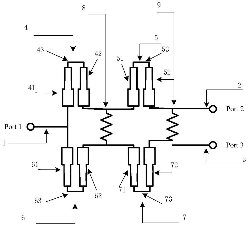
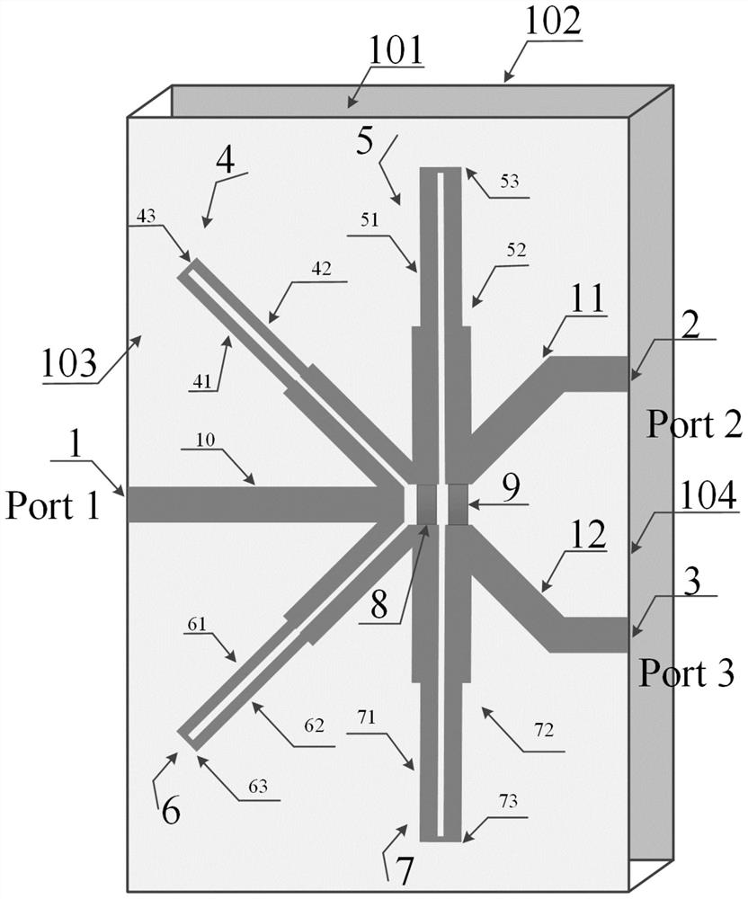
[0043] refer to figure 2 , the present embodiment provides a four-frequency power splitter based on stepped impedance coupled lines, including a dielectric substrate 101, the bottom surface of the dielectric substrate 101 is provided with a metal ground plate 102, and the top surface of the dielectric substrate 101 is provided with an input port feeder 1, a second An output port feeder 2, a second output port feeder 3 and two symmetrically arranged double-stage ladder impedance coupling lines, the two double-stage ladder impedance coupling lines are connected through an isolation resistor, and the input ends of the double-stage ladder impedance coupling lines are connected The input port feeder 1, and the input end of the double-stage ladder impedance coupling line are connected to the first output port feeder 2 and the second output port feeder 3 respectively.

[0044] The first double-stage ladder impedance coupling line includes a connected and uncoupled first ladder imped...

Embodiment 2

[0062] Because the four-frequency power divider based on the ladder impedance coupling line of the present invention is applied to the millimeter wave radar system, the simulation test results are as follows:

[0063] refer to Figure 8-10 , Figure 8 It is the S parameter simulation and test diagram of the four-frequency power divider in this example. It can be seen from the figure that the four frequency points of the four-frequency power divider based on the ladder impedance coupling line are 21.5GHz, 26.8GHz, 75.8GHz, 81.1GHz, these four frequency points correspond to the two most commonly used frequency bands of 24G and 77G in the field of millimeter wave radar. Figure 9 It is the S-parameter simulation and test chart of the isolation characteristics of the two power output ports of the four-frequency power divider in this example. It can be seen from the figure that the isolation at these four frequency points is less than -35dB. Figure 10 It is the S-parameter simul...


PUM


Abstract

The four-frequency power divider based on the stepped impedance coupling lines comprises a dielectric substrate and two double-section stepped impedance coupling lines arranged on the surface of the dielectric substrate, the double-section stepped impedance coupling lines comprise two sections of stepped impedance coupling lines which are connected and not coupled, and the two sections of stepped impedance coupling lines are arranged at an included angle. The two double-section stepped impedance coupling lines are symmetrically arranged and are connected through the isolation resistor, and the included angles of the two double-section stepped impedance coupling lines are close to each other; the input ends of the two double-section stepped impedance coupling lines are connected with the input port feeder line, and the input ends of the two double-section stepped impedance coupling lines are respectively connected with the first output port feeder line and the second output port feeder line; the four-frequency power divider utilizes a stepped impedance coupling line structure, has the advantages of small size, wide bandwidth, large frequency point span and the like, has good port isolation characteristics and power distribution characteristics, and is very suitable for a modern mobile communication system and a millimeter wave radar system.

Description

technical field [0001] The invention relates to the technical field of multi-frequency power divider design, in particular to a four-frequency power divider based on ladder impedance coupled lines. Background technique [0002] With the rapid development of economy and science and technology, diversified information services are required, so a variety of mobile communication standards have been proposed, such as GSM, CDMA, WIMAX, WLAN, etc. Limited spectrum resources put forward stricter requirements for the division of communication frequency bands, which also makes communication systems develop in the direction of small size and high integration. The power splitter has the function of distributing and synthesizing power, and is widely used in various microwave circuits. As an important component in the communication system, the power splitter is also developing towards the direction of miniaturization and high integration, so the research on the multi-band power splitter ...

Claims


Application Information

Patent Timeline
Patent Type & Authority Applications(China)
IPC IPC(8): H01P5/18
CPCH01P5/184
Inventor 王新怀李昕王文徐茵胡俊杰许洪扬
Owner XIDIAN UNIV
Why Eureka
Try Eureka