
Monitoring object movement identification method and system, terminal and storage medium

A technology for monitoring objects and recognizing models, applied in the field of image recognition, can solve the problems of fixed camera damage, camera field of view, unstable focal length, and high cost, and achieve the effects of improving modeling accuracy, wide application prospects, and reliable design principles.

Pending Publication Date: 2022-04-26
SHANDONG LUNENG SOFTWARE TECH
View PDF0 Cites 0 Cited by
  • Summary
  • Abstract
  • Description
  • Claims
  • Application Information

AI Technical Summary

Problems solved by technology

But this method is costly, and the fixed camera is also easy to be destroyed at the construction site
Although the use of dynamic monitoring equipment such as automatic tracking cameras or drones can save costs, due to the unfixed camera field of view and focal length, the existing image consistency comparison methods cannot obtain accurate recognition results
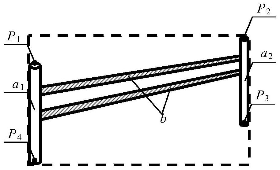
In addition, the existing image consistency comparison method is difficult to accurately detect the actual position and area of ​​the fence when the shape of the fence is changeable, and it is easy to cause false positives

Method used


Image

  • Monitoring object movement identification method and system, terminal and storage medium
  • Monitoring object movement identification method and system, terminal and storage medium
  • Monitoring object movement identification method and system, terminal and storage medium

Examples


Embodiment Construction

[0078] In order to enable those skilled in the art to better understand the technical solutions in the present invention, the technical solutions in the embodiments of the present invention will be clearly and completely described below in conjunction with the drawings in the embodiments of the present invention. Obviously, the described The embodiments are only some of the embodiments of the present invention, not all of them. Based on the embodiments of the present invention, all other embodiments obtained by persons of ordinary skill in the art without making creative efforts shall fall within the protection scope of the present invention.

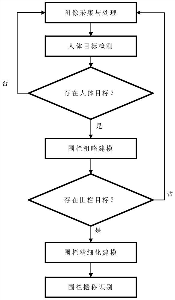
[0079] In order to solve the low recognition accuracy existing in existing image recognition methods, and can only perform consistent matching on images with a fixed field of view and focal length. The invention provides a monitoring object movement identification method, comprising the following steps:

[0080] Obtain monitoring image...


PUM


Abstract

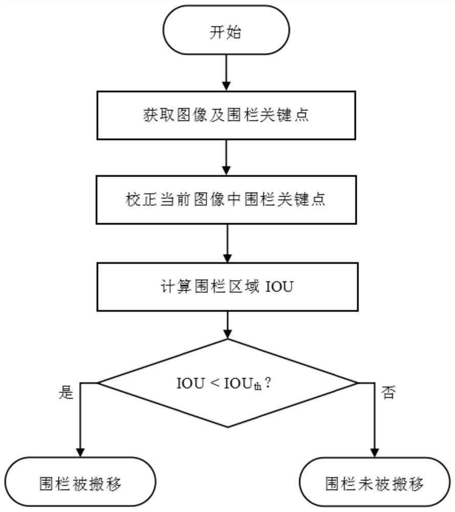
The invention relates to the technical field of image processing, and particularly provides a monitoring object movement recognition method and system, a terminal and a storage medium, and the method comprises the steps: recognizing the contour of a monitoring object from a monitoring image of a monitoring region through employing a target detection algorithm, and extracting a first key point set based on the contour of the monitoring object through employing a human body posture recognition model; calculating a homography matrix by using the feature points of the monitoring image and the standard image; mapping the first key point set to a standard image coordinate system by using a homography matrix, and calculating a polygon area enclosed by the first key point set on the standard image coordinate system; the area of a polygon defined by the key points of the monitoring object in the standard image serves as the standard area, and the metric value of the polygon area and the standard area is calculated; and comparing the measurement value with a set threshold value, and if the measurement value does not exceed the threshold value, judging that the monitored object is moved. The method can be applied to a dynamic monitoring scene, and the accuracy of an identification result in the dynamic monitoring scene is improved.

Description

technical field [0001] The invention relates to the technical field of image recognition, in particular to a monitoring object movement recognition method, system, terminal and storage medium. Background technique [0002] In scenes with complex environments such as power construction sites, some important equipment cannot be moved. For example, safety fences set around substations, high-voltage equipment, lifting work sites, etc. Once it is moved, it is very prone to safety accidents. Therefore, these important devices need to be monitored. The existing monitoring method is to install a camera in the monitoring area, and then perform image consistency comparison to confirm whether the monitoring object is in the original position. However, the cost of this method is relatively high, and the fixed camera is also easily destroyed at the construction site. Although the use of dynamic monitoring equipment such as automatic tracking cameras or drones can save costs, due to t...

Claims


Application Information

Patent Timeline
Patent Type & Authority Applications(China)
IPC IPC(8): G06V20/52G06V10/44G06V10/82G06T7/62
CPCG06T7/62G06T2207/10016G06T2207/20081G06T2207/20084
Inventor 陆顺邢宏伟薛念明刘涛李向阳张明岩段佳希
Owner SHANDONG LUNENG SOFTWARE TECH
Learn More