
Touch fingertip sensor and operating system and data processing method thereof

A data processing and sensor technology, which is applied in image data processing, instruments, image analysis, etc., can solve the problems of limited sensor sensing area, inconvenient sensor installation, and large sensor size, so as to facilitate deployment, wear, and expand the sensing area Effect

Pending Publication Date: 2022-04-26
CHONGQING UNIV
View PDF0 Cites 0 Cited by
  • Summary
  • Abstract
  • Description
  • Claims
  • Application Information

AI Technical Summary

Problems solved by technology

[0005] In view of this, the object of the present invention is to provide a tactile fingertip sensor and its operating system and data processing method, which solves the problem that the dual structure of the binocular camera causes the sensor to be bulky and overloaded, making it inconvenient to install the sensor on the mechanical finger. It reduces the problem of operational flexibility, and also solves the problem that the sensor with a planar structure has a limited sensing area and can only sense contact in a single direction

Method used


Image

  • Touch fingertip sensor and operating system and data processing method thereof
  • Touch fingertip sensor and operating system and data processing method thereof
  • Touch fingertip sensor and operating system and data processing method thereof

Examples


Embodiment 1

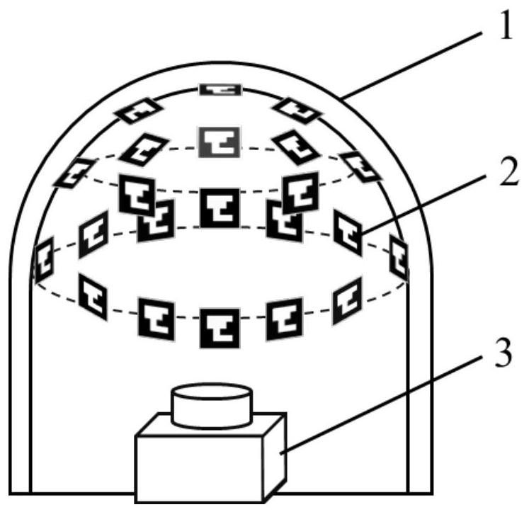
[0055] This embodiment describes a tactile fingertip sensor, which includes a tactile skin 1, a marker array sticker 2 and a monocular camera 3, the tactile skin 1 is used to convert physical contact into visual information that can be captured by the camera, and the marker array sticker 2 The markers in include position information and attitude information, which can be decoded and obtained by a computer, and the monocular camera 3 is used to capture the internal image of the tactile skin 1 . The marker array sticker 2 is pasted on the inner side of the tactile skin 1, and the bottom of the tactile skin 1 and the tactile fingertip sensor form a hollow cavity. The monocular camera 3 is installed on the bottom of the tactile fingertip sensor and is located in the hollow cavity. The domain covers the inner side of the tactile skin 1 .

[0056] Among them, the tactile skin 1 is the outermost layer of the tactile fingertip sensor. In order to fully reflect the deformation, it need...

Embodiment 2

[0060] This embodiment describes an operating system that includes the tactile fingertip sensor of Embodiment 1, the operating system is as Figure 4 As shown, the operating system also includes a host computer 7, the tactile fingertip sensor 5 is worn on the end of the mechanical finger 4 for grasping the object 6, and both the tactile fingertip sensor 5 and the mechanical finger 4 are connected to the host computer 7 through cables. When the mechanical finger 4 grasps the object 6, the surface of the elastic surface of the tactile fingertip sensor 5 and the tactile skin 1 will be deformed, which will cause the displacement of the mark array, and the monocular camera 3 will send the captured image to the host computer 7 for image processing and estimation. The force and deformation of the grasped object, and then control the force applied by the mechanical finger 4. For example, if it is judged that the applied force is too large, the control is turned down; if the applied for...

Embodiment 3

[0062] This embodiment describes the workflow of the operating system in Embodiment 2, that is, the data processing flow and method, the workflow is as follows Figure 8 As shown, the details are as follows:

[0063] S1. The monocular camera 3 captures the deformed image of the tactile skin 1 and transmits the deformed image to the host computer 7 .

[0064] When the mechanical finger 4 grabs the object, the tactile fingertip sensor 5 touches the object 6, and the elastic tactile skin 1 is deformed due to extrusion, and the deformed image of the tactile skin 1 is captured by the monocular camera 3, and the deformed image is transmitted to the host machine7.

[0065] S2. The host computer 7 internally runs the ArUco code marker detection program, and after judging that a sufficient number of markers have been detected, saves the three-dimensional position and pose information of each marker point.

[0066] The ArUco code consists of an equal-width black border and a specific ...


PUM


Abstract

The invention relates to the technical field of tactile sensors, in particular to a tactile fingertip sensor and an operating system and a data processing method.The tactile fingertip sensor comprises a tactile skin, a mark array sticker and a monocular camera, the mark array sticker is pasted on the inner side of the tactile skin, and the bottom of the tactile skin and the bottom of the tactile fingertip sensor form a hollow cavity; the monocular camera is installed at the bottom of the touch fingertip sensor and located in the hollow cavity, and the vision field of the monocular camera covers the inner side of the touch skin. According to the touch fingertip sensor disclosed by the invention, when a mechanical finger wearing the sensor touches an object, the sensor shoots an internal mark array image through the monocular camera, inputs the internal mark array image to the upper computer for image processing and data analysis, and finally converts the internal mark array image into various touch information; comprise the deformation condition of the contact surface, the size and direction of pressure at each marked position, contact torque and the like. By means of the design, contact in different directions can be sensed, distributed touch information is provided, and it is guaranteed that the sensor is compact in structure and light in weight.

Description

technical field [0001] The invention relates to the technical field of tactile sensors, in particular to a tactile fingertip sensor, an operating system and a data processing method thereof. Background technique [0002] Tactile perception is an important part for robots to obtain external information, and endowing robots with tactile sense is of great significance for the research of robot operation skills. Many different tactile sensing and perception systems have been designed at home and abroad for robot perception and manipulation tasks, such as object feature recognition, sliding detection, grasping stability evaluation, dexterous operation of manipulators, etc. According to the principle and shape of the sensor, the tactile sensors used on fingertips can be roughly divided into three categories: tactile arrays, bionic fingertips, and visual-tactile sensors. Due to the limited spatial resolution, it is difficult for tactile arrays and bionic fingertips to achieve high...

Claims


Application Information

Patent Timeline
Patent Type & Authority Applications(China)
IPC IPC(8): G06T17/00G06T7/70
CPCG06T17/00G06T7/70G06T2207/10024G06T2207/30204
Inventor 李睿彭柏皓李勇徐久铭黄江帅马铁东杨玥
Owner CHONGQING UNIV
Learn More