Thin seam coal mining machine

A technology for shearer and thin coal seam, which is applied to slitting machinery, cutting machinery, earth-moving drilling, etc., can solve the problems of large influence of force on the whole machine, small mining height of rear drum, and narrow mining height of shearer. , to achieve the effect of improving overall reliability, compact overall space, and reducing continuous power consumption

Pending Publication Date: 2022-04-26
SHANGHAI TIANDI MINING EQUIP TECH CO LTD +2
View PDF0 Cites 0 Cited by
  • Summary
  • Abstract
  • Description
  • Claims
  • Application Information

AI Technical Summary

Problems solved by technology

When the rear rocker arm of the thin coal seam suspension body shearer picks the upper knife, there will be a problem that the mining height of the rear drum is too small. The reason is that when the mining height increases, the cutting motor of the rear rocker arm will It will interfere with the upper coal platform left behind the bottom cutting knife of the front drum, so the overall mining height of this kind of shearer is too narrow to meet the mining requirements of my country's thin coal seam working face with large changes in seam thickness
[0003] In response to the above problems, the industry once proposed to divide the cutting part into a swing part and a fixed part, and set the cutting motor and the main body of the cutting transmission system in the fixed part, resulting in the structure of the fixed part being too complicated, and the left and right lengths of the overhanging section of the fuselage are skewed. Long and heavy, the problem of the center of gravity of the whole machine still has a great influence on the force of the whole machine
In addition, the shearer with a long body structure cannot perform the straight-feeding knife process similar to the short-wall shearer, and the oblique cutting at both ends takes a long time, which limits the mining efficiency to a certain extent.

Method used


Image

  • Thin seam coal mining machine
  • Thin seam coal mining machine
  • Thin seam coal mining machine

Examples


Embodiment Construction

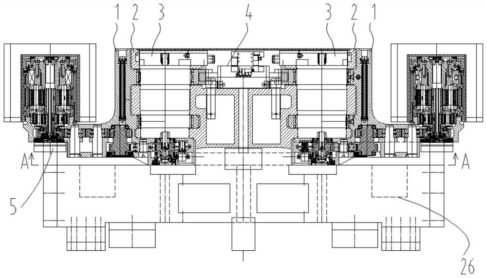
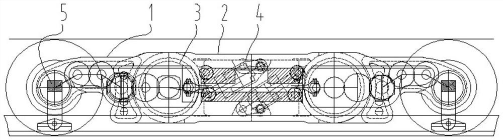
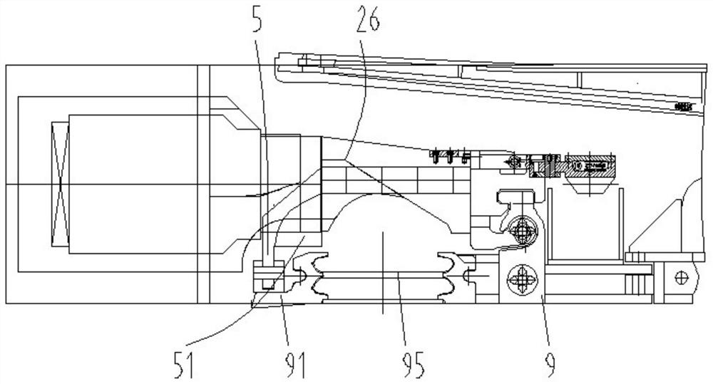
[0039] The invention discloses a thin coal seam shearer, such as Figure 1-6As shown, it includes a main body housing 2 and two swing arm housings 11 respectively hinged at the left and right ends of the front part of the main body housing. Each swing arm housing and the main body housing are separated by a The motor 3 is used as a hinge pin, and the cutting motor is fixed relative to the main body housing and swings relative to the swing arm housing. By using the cutting motor as a pin shaft, the left and right lengths of the main body casing are shortened, which is equivalent to shortening the left and right lengths of the suspension body section of the shearer, and the structure of the cutting mechanism is simplified. Due to this special articulated structure, each swing arm housing is driven by a cutting motor. On a double-drum shearer, the overall cutting power is greater than that of a single cutting motor, and the single cutting motor can be reduced during two-way minin...


PUM


Abstract

The invention relates to a thin seam mining machine which comprises a main body part shell and two swing arm shells hinged to the left end and the right end of the front portion of the main body part shell respectively, a cutting motor is arranged between each swing arm shell and the main body part shell to serve as a hinge pin shaft, and a cover plate is installed at an opening in the front end of the main body part shell. A closed oil cylinder installation cavity is defined by the swing arm shells, the main body shell, the cutting motor and the cover plate, oil cylinders driving the left swing arm shell and the right swing arm shell to swing are installed in the oil cylinder installation cavity, the rear portion of the main body shell is provided with a left coal flow rear channel and a right coal flow rear channel, the coal flow rear channels are grooves which extend from front to back and are provided with downward groove openings, and the coal flow rear channels are communicated with the oil cylinder installation cavity. And the rear end of the groove is closed. The large mining range and the large cutting power can be provided, the machine body can be shortened, and the coal flow loading effect is improved.

Description

technical field [0001] The invention relates to a coal shearer, especially a thin coal seam shearer, which has a large mining range and high cutting power. Background technique [0002] On the existing thin coal seam shearer, the cutting motor is usually located on the rocker arm and swings with the swing of the rocker arm. When the rear rocker arm of the thin coal seam suspension body shearer picks the upper knife, there will be a problem that the mining height of the rear drum is too small. The reason is that when the mining height increases, the cutting motor of the rear rocker arm will It will interfere with the upper coal platform left behind the bottom cutting knife of the front drum, so the overall mining height of this kind of shearer is too narrow, and cannot adapt to the mining requirements of large changes in seam thickness in thin coal seam working faces in my country. [0003] In response to the above problems, the industry once proposed to divide the cutting pa...

Claims


Application Information

Patent Timeline
Patent Type & Authority Applications(China)
IPC IPC(8): E21C35/00E21C25/06
CPCE21C35/00E21C25/06
Inventor 章立强贠瑞光王振乾胡璟胡滔董超顾恩洋郭岱罗毅王江
Owner SHANGHAI TIANDI MINING EQUIP TECH CO LTD
Why Eureka
Try Eureka