
Pulse source pulse generation circuit, control method and device, equipment and storage medium

A technology of pulse generation circuit and pulse source, which is applied in the direction of electric pulse generator circuit and energy storage element to generate pulses, etc., can solve the problems of high internal power loss, low energy storage density, long charging time, etc., to reduce power loss, The effect of high energy storage density and shortened charging time

Pending Publication Date: 2022-04-22
CHONGQING UNIV
View PDF0 Cites 0 Cited by
  • Summary
  • Abstract
  • Description
  • Claims
  • Application Information

AI Technical Summary

Problems solved by technology

[0004] Aiming at the shortcomings of the existing methods, the present application proposes a pulse source pulse generating circuit, control method, device, equipment, and storage medium to solve the problem of long charging time or internal power loss in electric pulse generating devices in the prior art. Technical problems with defects such as high or low energy storage density

Method used


Image

  • Pulse source pulse generation circuit, control method and device, equipment and storage medium
  • Pulse source pulse generation circuit, control method and device, equipment and storage medium
  • Pulse source pulse generation circuit, control method and device, equipment and storage medium

Examples


Embodiment Construction

[0084] The present application is described in detail below, and examples of embodiments of the present application are shown in the drawings, wherein the same or similar reference numerals denote the same or similar components or components having the same or similar functions throughout. Also, detailed descriptions of known technologies will be omitted if they are not necessary to illustrate the features of the present application. The embodiments described below by referring to the figures are exemplary only for explaining the present application, and are not construed as limiting the present application.

[0085] Those skilled in the art can understand that, unless otherwise defined, all terms (including technical terms and scientific terms) used herein have the same meanings as commonly understood by those of ordinary skill in the art to which this application belongs. It should also be understood that terms, such as those defined in commonly used dictionaries, should be ...


PUM


Abstract

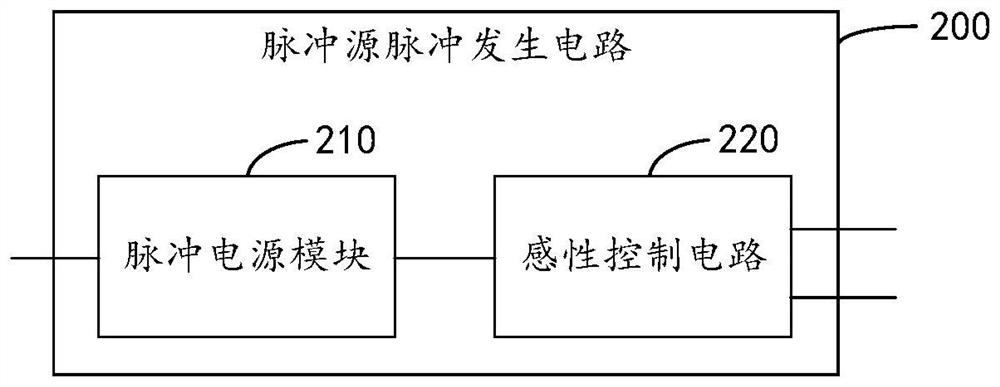
The embodiment of the invention provides a pulse source pulse generation circuit, a control method and device, equipment and a storage medium. The pulse source pulse generation circuit comprises a pulse power supply module; the inductive control circuit comprises a control input end and two complementary control output ends; wherein the control input end is connected with the pulse power supply module; one control output is configured to be grounded in a charging mode, and the other control output is configured to be connected with a load in a discharging mode. According to the embodiment of the invention, the pulse power supply module charges the inductive control circuit by outputting the pulse voltage source, so that the charging time is shortened, the internal electric energy loss of the electric pulse generation device is reduced, and energy conservation and consumption reduction are realized; higher energy storage density can be obtained by adopting an inductive control circuit through an inductive energy storage technology, and the amplitude of the output current pulse does not change along with the change of load characteristics.

Description

technical field [0001] The present application relates to the technical field of pulse circuits, and in particular, the present application relates to a pulse source pulse generating circuit, a control method, a device, a device, and a storage medium. Background technique [0002] Electric pulse generating devices have a wide range of applications in the field of modern science and technology, such as biomedicine, semiconductor testing, superconducting testing, plasma physics, controlled nuclear fusion, electromagnetic propulsion, high-power lasers with repetitive pulses, high-power radar, strong Generation of charged particle beams and intense pulsed electromagnetic radiation. [0003] Existing electric pulse generating devices usually have defects such as long charging time, high internal power loss, and low energy storage density. Contents of the invention [0004] Aiming at the shortcomings of the existing methods, the present application proposes a pulse source pulse...

Claims


Application Information

Patent Timeline
IPC IPC(8): H03K3/57
CPCH03K3/57
Inventor 董守龙姚陈果余亮
Owner CHONGQING UNIV
Learn More