
Optical sensing demodulation module and optical sensing system

A technology of sensing solutions and light-emitting modules, which is applied in the field of optical sensing, can solve problems such as large amount of calculation, reduced accuracy of demodulation modules, and back-and-forth fluctuations of lasers, so as to improve measurement accuracy, reduce calculation amount, and improve accuracy.

Pending Publication Date: 2022-04-22
OTN INTELLIGENT TECH (SUZHOU) CO LTD
View PDF0 Cites 0 Cited by
  • Summary
  • Abstract
  • Description
  • Claims
  • Application Information

AI Technical Summary

Problems solved by technology

[0004] However, after using the feedback power control circuit to compensate the power of the laser, the power of the laser will fluctuate back and forth in a small range
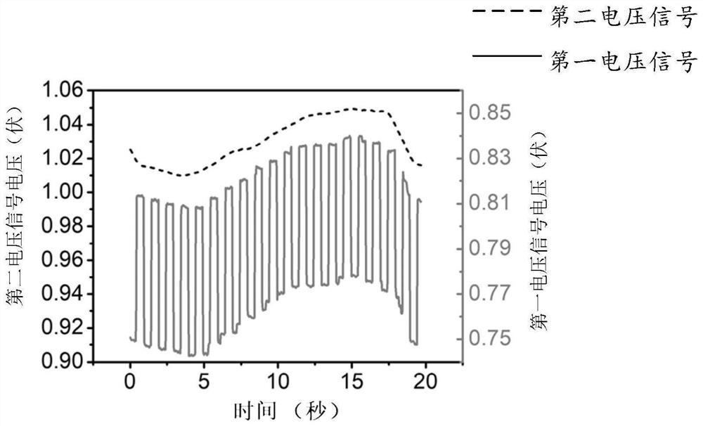
This kind of fluctuation is irrelevant for the optical communication industry, but for the optical sensing application mainly based on analog signal modulation, the fluctuation of laser power will cause fluctuations in the baseline of the final sensing signal, and the existence of the baseline will make In the process of analyzing the sensing signal, it is difficult to judge whether the fluctuation of the sensing signal comes from the modulation of the optical sensor by the external test parameters or the change of the laser power. Impact of range changes
At this time, some sensor signal changes caused by changes in external parameters with small modulation amplitudes cannot be detected, resulting in a decrease in the accuracy of the demodulation module
[0005] In the prior art, the sensing signal is fitted by the upper computer software to remove the baseline of the sensing signal, but this method requires a large amount of calculation, and this method is based on the saved data for fitting calculation, which cannot be done to real-time removal of the baseline
At the same time, slight changes in laser power may cause large errors in the baseline fitting of the host computer software

Method used


Image

  • Optical sensing demodulation module and optical sensing system
  • Optical sensing demodulation module and optical sensing system
  • Optical sensing demodulation module and optical sensing system

Examples


Embodiment Construction

[0032] The terms "first", "second", "third" and so on are only used for distinguishing descriptions, and do not represent sequence numbers, nor can they be understood as indicating or implying relative importance.

[0033] In addition, the terms "horizontal", "vertical", "overhanging" and the like do not mean that the components are absolutely horizontal or overhanging, but may be slightly inclined. For example, "horizontal" only means that its direction is more horizontal than "vertical", and it does not mean that the structure must be completely horizontal, but can be slightly inclined.

[0034] In the description of the present application, it should be noted that the orientation or positional relationship indicated by the terms "inner", "outer", "left", "right", "upper", "lower" etc. are based on the Orientation or positional relationship, or the orientation or positional relationship that the application product is usually placed in use, is only for the convenience of des...


PUM


Abstract

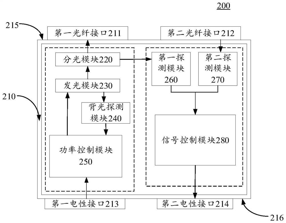
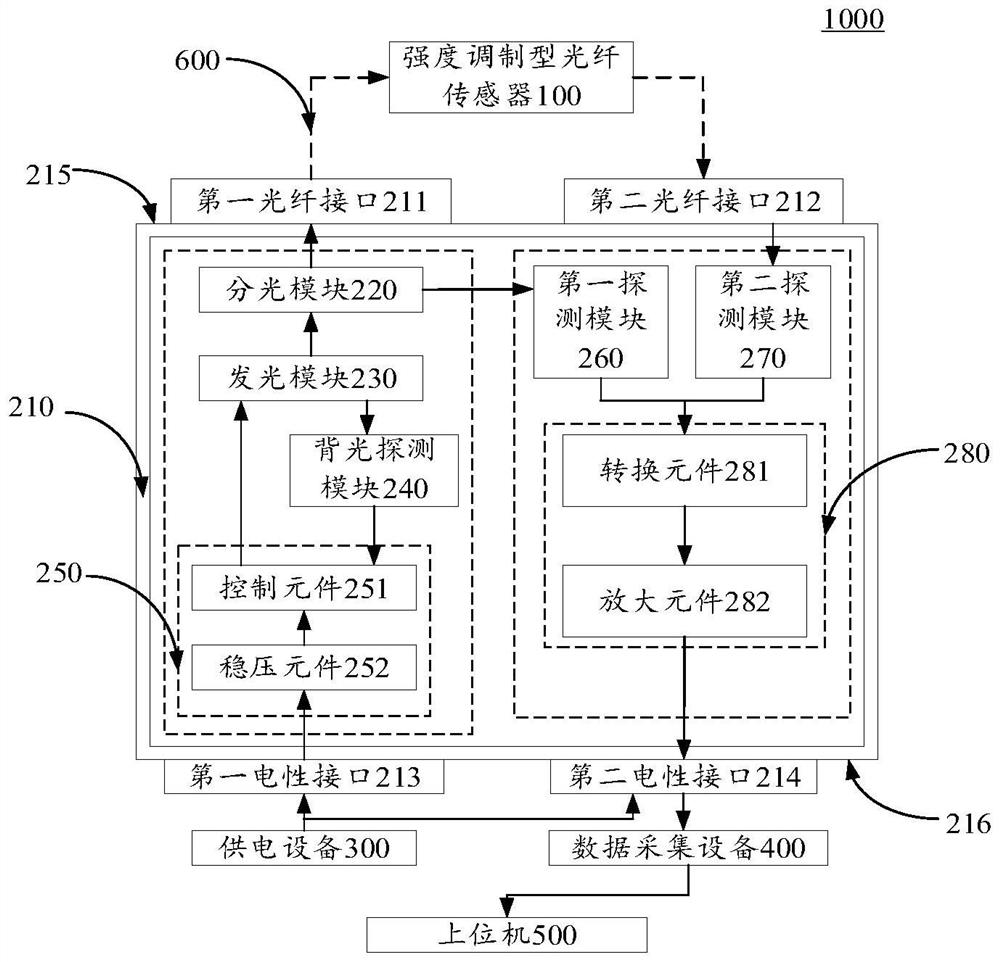
The invention provides an optical sensing demodulation module and an optical sensing system. The optical sensing demodulation module comprises a shell, a power control module, a light emitting module, a backlight detection module, a light splitting module, a signal control module, a first detection module and a second detection module, the shell is provided with a first optical fiber interface, a second optical fiber interface, a first electrical interface and a second electrical interface; the power control module is connected with the first electrical interface; the light-emitting module is arranged in the shell and is connected with the power control module; the backlight detection module is arranged in the shell and is connected with the light-emitting module and the power control module; the light splitting module is arranged in the shell and is connected with the light emitting module and the first optical fiber interface; the signal control module is arranged in the shell and is connected with the second electrical interface; the first detection module is arranged in the shell and is connected with the light splitting module and the signal control module; and the second detection module is arranged in the shell and is connected with the second optical fiber interface and the signal control module. And a signal base line generated by light source power fluctuation in a sensing signal is effectively removed.

Description

technical field [0001] The present application relates to the field of optical sensing technology, and in particular to an optical sensing demodulation module and an optical sensing system. Background technique [0002] The intensity modulation optical fiber sensor is a sensor that converts the state of the measured physical parameter into a measurable optical signal. The working principle of the intensity-modulated optical fiber sensor is to send the beam emitted by the laser into the modulator through the optical fiber, and change the light intensity of the optical signal in the modulator to become a modulated optical signal. After modulation, the modulated light is transmitted through the optical fiber. The signal is sent to the demodulation module, and the measured value of the physical parameter to be measured is obtained through the demodulation module. [0003] In practical applications, lasers usually reduce the output optical power due to temperature changes or agi...

Claims


Application Information

Patent Timeline
Patent Type & Authority Applications(China)
IPC IPC(8): G01D5/26
CPCG01D5/268
Inventor 刘晓海姜天昊
Owner OTN INTELLIGENT TECH (SUZHOU) CO LTD
Learn More