
Device for measuring parallelism of micro electrode plate group

A technology of micro-electrodes and parallelism, which is applied in the direction of measuring devices, electric devices, and fluid devices, etc., can solve the problems of inability to detect the parallel position of micro-electrode plate groups, and achieve the effect of ensuring the detection environment

Active Publication Date: 2022-04-22
四川文理学院
View PDF7 Cites 0 Cited by
  • Summary
  • Abstract
  • Description
  • Claims
  • Application Information

AI Technical Summary

Problems solved by technology

[0003] The purpose of the present invention is to provide a device for measuring the parallelism of micro-electrode plate groups to solve the problem that the prior art cannot better detect the parallel position of micro-electrode plate groups

Method used


Image

  • Device for measuring parallelism of micro electrode plate group
  • Device for measuring parallelism of micro electrode plate group

Examples


Embodiment 1

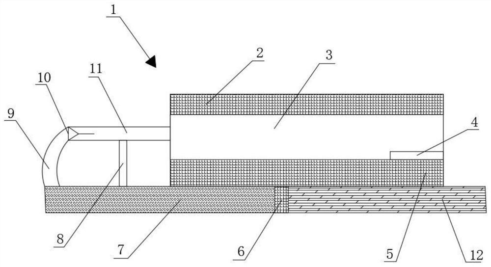
[0029] A device for measuring the parallelism of a micro-electrode plate group, comprising a device body 1, the device body 1 includes a functional base, and a test cavity 3 for parallelism detection is fixedly connected to the functional base. The chamber 3 contains a fluid medium.

[0030] It should be noted that a test chamber 3 is provided in the device body, and the micro-electrode plate group to be tested is arranged in the test chamber 3. Preferably, the fluid medium can be air, and air is selected as the fluid medium in the parallelism measurement. On the one hand, it can ensure that the electrode plate will not be damaged during the test as much as possible; on the other hand, the air is easy to obtain and will not cause waste of resources. In detail, one side or the surrounding side of the test chamber 3 described in this application is a see-through structure, and testers can intuitively observe the state and results of the internal test through the chamber wall. S...

Embodiment 2

[0043] Please refer to the attached figure 2 , on the basis of Example 1, this example uses a high-speed camera to record the process of the reciprocating jump of the droplet at a rate of 60,000 frames per second, and uses image collection software to obtain a motion video, and finally calculates the speed, acceleration, and displacement through an algorithm. Analysis of parameters.

[0044] Specifically, by changing the distance between the two micro-electrode plates so that the vertical distance between the two micro-electrode plates is L=5.5mm-14.5mm, the deformation process and electric current of the droplet on the surface of the micro-electrode plates were studied. threshold.

[0045] When a droplet with a radius of 1.0mm is placed on the surface of the microelectrode plate with L=5.5mm, when the applied voltage E≥3.2KV, the droplet begins to elongate, and then has a tendency to leave the microelectrode plate, such as figure 2 shown. In the present embodiment, the i...


PUM


Abstract

The invention relates to the technical field of location degree detection, in particular to a device for measuring the parallelism of a micro electrode plate group, which comprises a device body, a functional base is arranged in the device body, a test cavity for detecting the parallelism is fixedly connected to the functional base, a fluid medium is arranged in the test cavity, and the fluid medium is communicated with the functional base. The arrangement of the test cavity can ensure that visual and complete parallelism detection can be carried out on the to-be-detected micro electrode plate group, specifically, after the to-be-detected micro electrode plate group is placed in the test cavity, the electrode plates are electrified, an electric field is generated immediately, an electric field force is generated under the action of the electric field, and the parallelism of the to-be-detected micro electrode plate group is detected. And the electric field force and the medium liquid jointly form an electric field environment with a driving effect, so that a subsequent detection environment is effectively guaranteed.

Description

technical field [0001] The invention relates to the technical field of position degree detection, and relates to a device for measuring the parallelism of micro-electrode plate groups. Background technique [0002] With the emergence of high-precision equipment, more and more equipment and products are biased toward micro-equipment. Their volume and functions have gradually become smaller and more precise. Therefore, each micro-product needs strict quality control and monitoring. Detection, in the prior art, large-scale laser detection devices are often used to detect the position of products, especially widely used in the field of parallel leveling, but due to the limitations of the laser itself, there will be some occluded planes that cannot be directly irradiated or directly The problem of data monitoring is generally adjusted manually at this time, but in the process of manual adjustment, the problem of joint adjustment errors will inevitably occur. There is no good solu...

Claims


Application Information

Patent Timeline
Patent Type & Authority Applications(China)
IPC IPC(8): G01B13/19G01B7/312
CPCG01B13/19G01B7/312Y02E60/10
Inventor 李斌熊伦
Owner 四川文理学院
Learn More