Underground intelligent water distributor

A water distributor and intelligent technology, applied in wellbore/well components, machines/engines, production fluids, etc., can solve problems such as pushing difficult communication cables, damaging the stability of electronic control systems, etc., to achieve easy control, fast and controllable. Effect

Active Publication Date: 2022-04-22
DONGYING BAIHUA GASOLINEEUM TECH DEV
View PDF0 Cites 0 Cited by
  • Summary
  • Abstract
  • Description
  • Claims
  • Application Information

AI Technical Summary

Problems solved by technology

[0003] The purpose of the present invention is to set the support ring on the outer wall of the water distributor, and follow the water distributor to move inside the water injection well. The four rollers on the support ring are supported on the inner wall of the water injection well, which is convenient for the water injection pipeline and isolation. The alignment at the middle position of the device is rotated under the traction of external equipment through the elliptical dragging plate, so that one end of the water injection pipe that penetrates into the interior of the water injection well can be driven deep into the interior of the water injection well by the support ring, and the elliptical dragging plate is used in the outside world Under the traction of the equipment, it rotates and drives the power generation equipment inside the power generation box to generate electricity, so that the water distributor at the corresponding position can be supplied with power by the power generated by the equipment inside the power generation box, which is less affected by the power supply transmitted by the communication cable, and solves the problem of deep water injection During the injection well process, the water injection pipeline is difficult to align with the packer, it is difficult to push the water injection pipeline deep after the water injection pipeline penetrates into the water injection well, and the damage of the communication cable during the penetration of the water injection pipeline affects the stability of the electronic control system. And propose a kind of downhole intelligent water distributor

Method used


Image

  • Underground intelligent water distributor
  • Underground intelligent water distributor
  • Underground intelligent water distributor

Examples


Embodiment 1

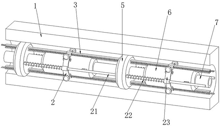
[0025] Example 1: See Figure 1-2 As shown, a downhole intelligent water distributor includes a water injection well 1, a packer 5, a water distributor 6 and a water injection pipeline 7. A number of evenly distributed packers 5 are connected inside the water injection well 1, and the middle position of the packer 5 is A water injection pipeline 7 is connected to the water injection pipeline 7, and a water distributor 6 is connected to the side of the outer wall of the water injection pipeline 7 close to the packer 5; several packers 5 are connected inside the water injection well 1, and the space between every two adjacent packers 5 The distance between them is equal, the packer 5 is in close contact with the inner wall of the water injection well 1, and the outer side of the water injection pipeline 7 is connected with a water distributor 6 at the same distance, and the water distributors 6 are connected to each other through communication cables and data communication transm...

Embodiment 2

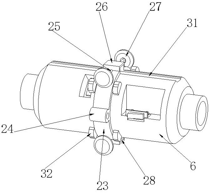
[0026] Example 2: See Figure 3-8 As shown, the upper surface of the water distributor 6 is provided with a moving mechanism 3, and the moving mechanism 3 includes an installation groove 31. The upper and lower surfaces of the water distributor 6 are connected with a sliding cavity 312 at the position corresponding to the installation groove 31. One side of the outer wall of the water distributor 6 is provided with an elastic Cavity 39, a third spring 38 is connected to both sides of the inner rear surface of the elastic cavity 39, one end of the third spring 38 is connected to the inner rear surface of the elastic cavity 39, and the other end is connected to the limiting plate 33 on the extrusion block 310, The front end of the third spring 38 is connected with an extruding block 310, and the middle position of the inner rear surface of the elastic chamber 39 is connected with a second pressure sensor 37. The second pressure sensor 37 can detect the pressure on the extruding b...

Embodiment 3

[0027] Example 3: See Figure 9-10As shown, a power supply mechanism 4 is provided at the position corresponding to the sliding cavity 312 on the outer wall of the water distributor 6, and the power supply mechanism 4 includes an interlocking cavity 42. The position corresponding to the interlocking cavity 42 on the outer wall of the sliding cavity 312 is connected to a second Gear 43, the position corresponding to the second gear 43 on the inner side wall of the sliding cavity 312 is connected with the fourth gear column through the rotating shaft, and the second gear 43 is embedded with the tooth groove on the drag plate 314 through the fourth gear column on the coaxial The first gear 41 is connected to the position corresponding to the second gear 43 on the inner side wall of the interlocking chamber 42, and a power generation chamber 46 is opened inside the water distributor 6 near the position of the first gear 41, and the inner lower surface of the power generation chambe...


PUM


Abstract

The invention relates to a water distributor technology, and aims to solve the problems that a water injection pipeline is difficult to align with a packer in the process of penetrating into a water injection well, the water injection pipeline is difficult to push deep into the water injection well after penetrating into the water injection well, and the stability of an electric control system is affected by damage of a communication cable in the penetrating process of the water injection pipeline. The underground intelligent water distributor comprises a water injection well, a packer, a water distributor body and a water injection pipeline. The supporting ring moves in the water injection well along with the water distributor, so that the water injection pipeline is aligned with the middle position of the packer under the supporting of four rollers on the supporting ring, and one end of the water injection pipeline penetrating into the water injection well can penetrate into the water injection well under the driving of the supporting ring through the rotation of the dragging plate; the dragging plate rotates to drive the power generation equipment to generate power, so that the water distributors at the corresponding positions can supply power through the power generated by the equipment in the power generation box, and the influence of power supply transmitted by the communication cable is small.

Description

technical field [0001] The invention relates to water distributor technology, in particular to an underground intelligent water distributor. Background technique [0002] The water distributor is a special downhole tool used for quantitative water injection of each oil layer during layered water injection. It is mainly composed of a water distribution main body, a water distribution nozzle, a water nozzle body, a gland and a sealing ring; After the pipeline enters the water injection well, it needs to pass through multiple packers to reach the bottom of the water injection well. When the water injection pipeline is moving inside the water injection well, one end of the water injection pipeline needs to be aligned with the middle position of the packer , to prevent the water injection pipeline from being blocked and difficult to pass through the packer to reach the bottom of the water injection well. During the process of moving the water injection pipeline inside the water i...

Claims


Application Information

Patent Timeline
IPC IPC(8): E21B23/01E21B43/20F03G7/00
CPCE21B23/01E21B43/20F03G7/00
Inventor 尚兴宾陈磊刘春兴赵磊高朋王学用刘朋朋周聪聪
Owner DONGYING BAIHUA GASOLINEEUM TECH DEV
Why Eureka
Try Eureka