Closestool flushing system

A toilet and pressure technology, applied in the field of sanitary ware, can solve problems affecting user experience, high noise, and low flushing force, and achieve the effects of avoiding gas-liquid mixing and dry spraying, reducing noise, and improving flushing performance

Pending Publication Date: 2022-04-22
XIAMEN R&T PLUMBING TECH
View PDF0 Cites 0 Cited by
  • Summary
  • Abstract
  • Description
  • Claims
  • Application Information

AI Technical Summary

Problems solved by technology

[0003] At present, the main flushing structure of the pressure toilet flushing system generally sprays directly to the sewage pipe of the toilet through a small hole, and uses the Venturi principle to make the sewage pipe produce a siphon. The flushing force of this flushing system is small, and the noise is relatively large when flushing , there is splashing phenomenon, which greatly affects the user experience

Method used


Image

  • Closestool flushing system
  • Closestool flushing system
  • Closestool flushing system

Examples


Embodiment 1

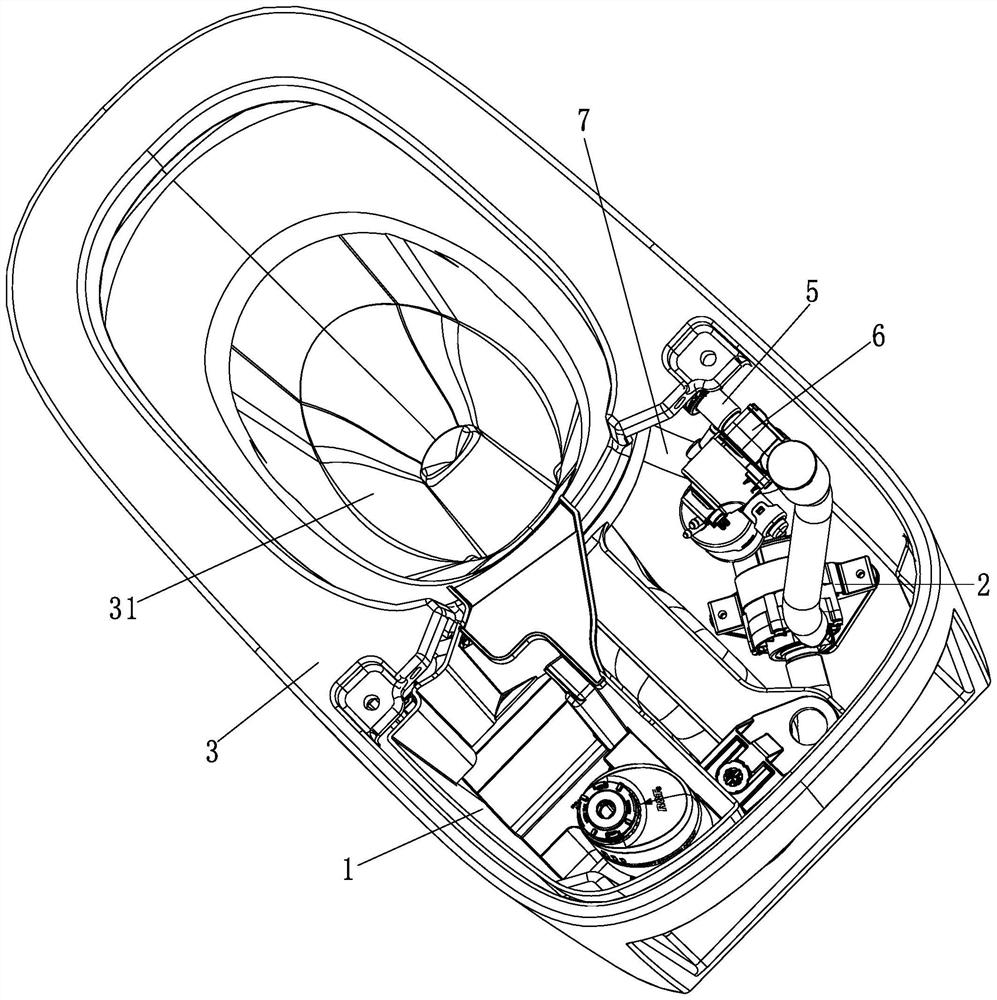
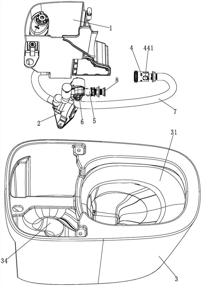
[0033] See Figure 1 to Figure 6 As shown, a kind of toilet flushing system of the present embodiment comprises:

[0034] A pressure water source for providing pressure water;

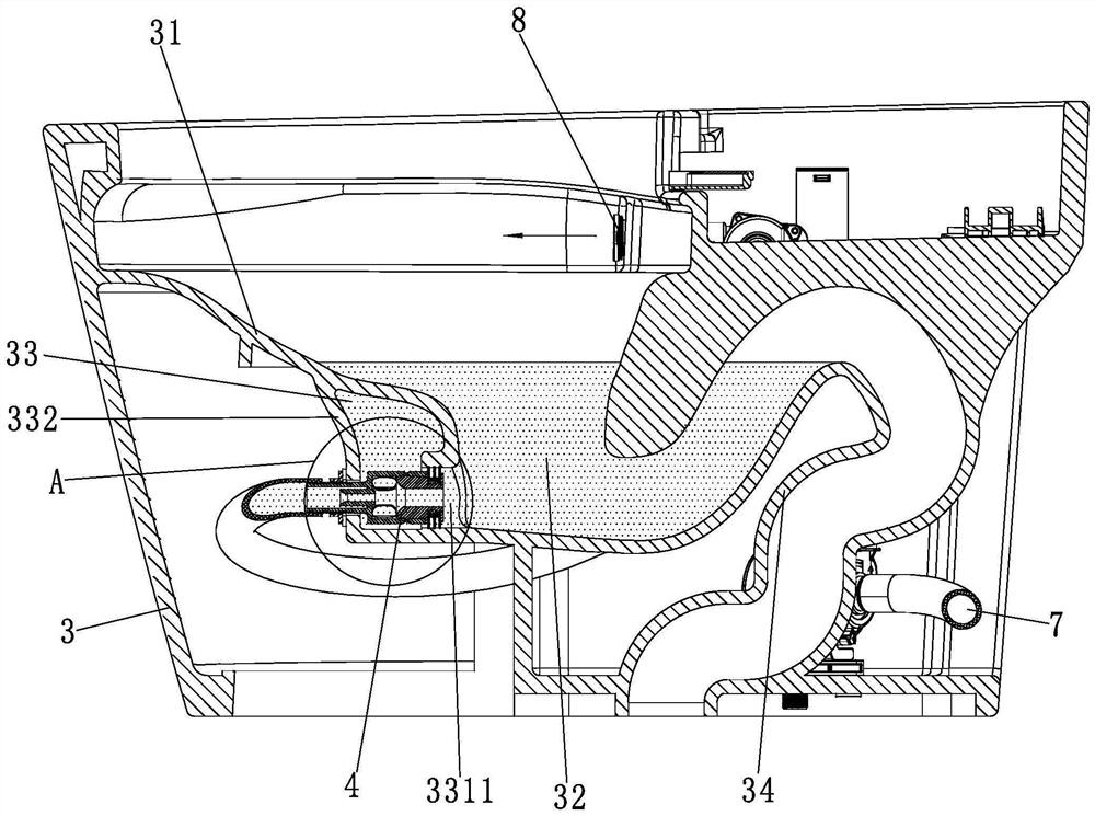
[0035] Toilet 3, toilet 3 has bedpan 31, and the bottom of bedpan 31 has the water sealing water that is used to form water seal 32, and the bottom of bedpan 31 is provided with a water storage chamber 33, and water storage chamber 33 has the anterior cavity wall 331 that is arranged oppositely and rear The chamber wall 332, the front chamber wall 331 is provided with spray holes 3311, the rear chamber wall 332 is provided with installation holes 3321, the water storage chamber 33 communicates with the water seal 32 through the spray holes 3311;

[0036] The flow increasing device 4 is installed in the installation hole 3321, the inlet of the flow increasing device 4 is connected with the pressure water source, the pressure water source provides pressure water to the flow increasing device 4, and the ...

Embodiment 2

[0053] Embodiment 2 (not shown)

[0054] This embodiment is basically the same as Embodiment 1, the only difference being:

[0055] In this embodiment, the flow increasing device is only provided with injection channels, and the cross-sectional area of ​​the outlet of the injection channel (that is, the outlet of the flow increasing device) is smaller than the cross-sectional area of ​​the injection hole, and the outlet of the injection channel and the inlet of the injection hole are arranged at intervals ( That is, the outlet of the flow increasing device and the inlet of the injection hole are arranged at intervals), and the outlet of the injection channel sprays water flow to the inlet of the injection hole. By adopting this structural design, the flow increasing device of this embodiment can make use of the Venturi principle to make the storage The water in the water chamber is sucked into the inlet end of the jet hole, and the water sucked into the inlet end of the jet ho...


PUM


Abstract

The invention discloses a closestool flushing system which comprises a pressure water source, a flushing device and a flushing device. The closestool is provided with a bedpan, the bottom of the bedpan is provided with water seal water used for forming water seal, the bottom of the bedpan is provided with a water storage cavity, the water storage cavity is provided with a front cavity wall and a rear cavity wall which are oppositely arranged, the front cavity wall is provided with an injection hole, the rear cavity wall is provided with a mounting hole, and the water storage cavity is communicated with the water seal through the injection hole; the flow increasing device is mounted in the mounting hole, an inlet of the flow increasing device is communicated with a pressure water source, the pressure water source provides pressure water to the flow increasing device, water sprayed out of an outlet of the flow increasing device is sprayed to the water seal through the spraying hole, and the flow increasing device is configured to take water in the water storage cavity out of the spraying hole according to the Venturi principle; and before the water level of the water storage cavity drops until the water storage cavity can be communicated with the external atmosphere through the injection hole, the pressure water source stops supplying water to the flow increasing device.

Description

technical field [0001] The invention relates to the technical field of sanitary ware, in particular to a toilet flushing system. Background technique [0002] The toilet usually relies on the combination of the main flush water and the washing water, and the dirt on the wall of the urinal is washed away by the washing water, and then the main flush water drives the dirt washed down by the washing water to be discharged through the sewage pipe. [0003] At present, the main flushing structure of the pressure toilet flushing system generally sprays directly to the sewage pipe of the toilet through a small hole, and uses the Venturi principle to make the sewage pipe produce a siphon. The flushing force of this flushing system is small, and the noise is relatively large when flushing , there is a splashing phenomenon, which greatly affects the user experience. Contents of the invention [0004] In order to solve the above technical problems, the present invention provides a t...

Claims


Application Information

Patent Timeline
IPC IPC(8): E03D1/38E03D11/06E03D9/14E03D9/16
CPCE03D1/38E03D11/06E03D9/14E03D9/16E03D2201/40
Inventor 钟志军陈海滨赖新兆
Owner XIAMEN R&T PLUMBING TECH
Why Eureka
Try Eureka