
Automatic fault detection method for crane operating rod controller

An automatic detection and operating rod technology, applied in the direction of transportation and packaging, load suspension components, safety devices, etc., can solve the problems of difficult judgment, inconvenient video, limited level, etc., and achieve the effect of saving maintenance time and cost

Pending Publication Date: 2022-04-22
UNIV OF SCI & TECH LIAONING
View PDF0 Cites 0 Cited by
  • Summary
  • Abstract
  • Description
  • Claims
  • Application Information

AI Technical Summary

Problems solved by technology

[0002] In the daily maintenance process of large cranes, the following problems often occur: due to the limited level of on-site maintenance personnel, when the operating lever is operated to a certain gear, the corresponding mechanism does not operate or malfunctions. There are two reasons for the failure: one is the contactor or relay failure of the output part, and the other is the contact failure of the crane operating rod. The contactors or relays of the output part have their own functions, such as: main lifting up, main lifting Lifting and lowering, brakes, second gear speed regulation, etc., maintenance personnel can easily check their functions
However, because the IO indicator light on the PLC is very small, the video is sometimes blurry, and it is often inconvenient to video in foreign countries, so we can only send us photos. Sometimes the IO indicator light on the PLC cannot be clearly seen from the photos, and it is difficult to judge

Method used


Image

  • Automatic fault detection method for crane operating rod controller
  • Automatic fault detection method for crane operating rod controller
  • Automatic fault detection method for crane operating rod controller

Examples


Embodiment Construction

[0037] The specific embodiments provided by the present invention will be described in detail below in conjunction with the accompanying drawings.

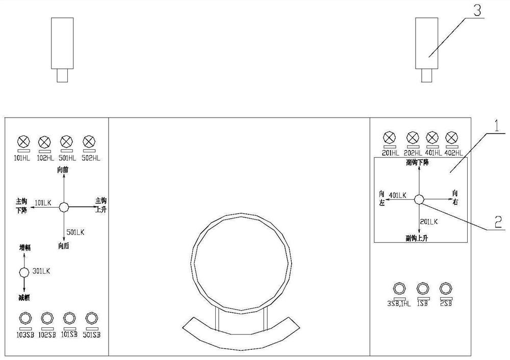
[0038] Such as Figure 1-9 As shown, a fault automatic detection method for a crane joystick controller includes the following:

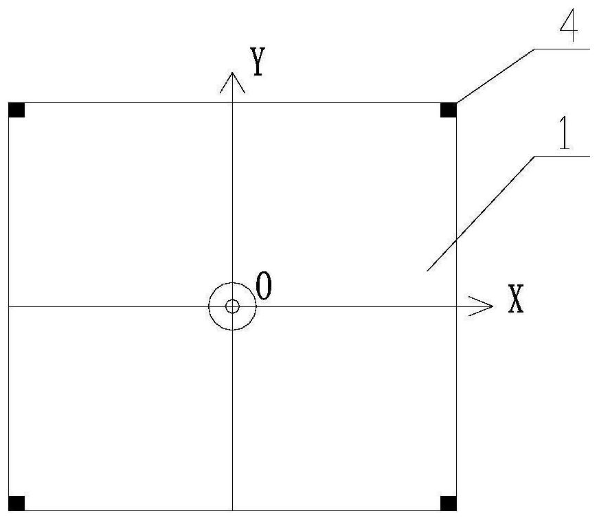
[0039] Step 1. Install the camera 3 directly above the crane operating platform, and set the panel 1 on the joystick controller 2 of the linkage platform, and the joystick controller 2 is located at the center of the panel 1.

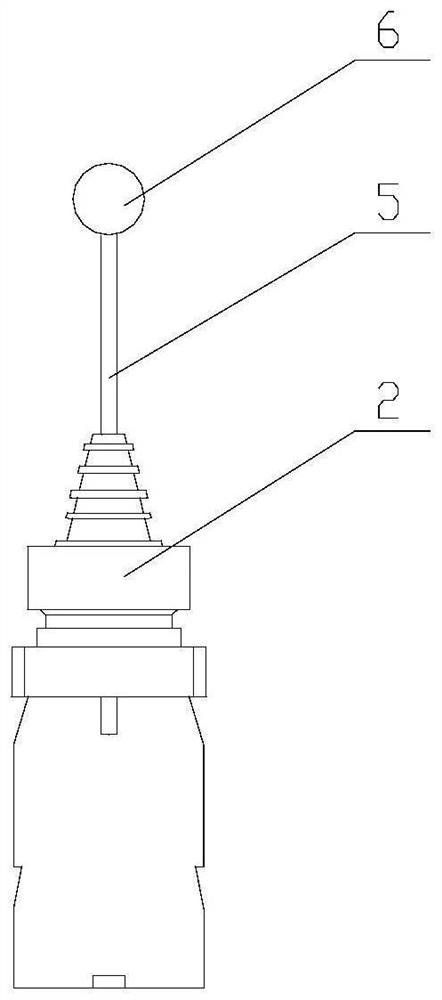
[0040] Step 2: Set marker one 4 on the panel 1 of the crane operating rod controller 2 , and set marker two on the handle 6 of the operating rod controller 2 .

[0041] The disk surface 1 of the crane joystick controller 2 is a square with a white background. If the linkage platform is a white paint surface, the disk surface 1 can be a square area on the upper part of the linkage platform, or a metal square with a white background can be fixed on the linkage platform. Or a non-...


PUM


Abstract

The invention provides an automatic fault detection method for a crane operating rod controller. The automatic fault detection method comprises the steps that a camera is installed above a crane operating table, a disc face is arranged at the position of the operating rod controller of a linkage table, a first marker is arranged on the disc face, and a second marker is arranged on a handle of the operating rod controller; when the crane operating rod controller breaks down, the camera collects and processes images, the range of the disc face is recognized through the first marker, and the position of the handle on the disc face is recognized through the second marker. The operation position and the gear of the operation rod controller are determined through the position of the handle on the disc surface; and the expert system determines the IO corresponding condition of the crane PLC according to the operation position and the gear of the operation rod controller, compares the IO corresponding condition with the IO actual condition of the PLC, and outputs the position of a fault IO point. Under the condition that technicians of a crane manufacturer are not on site, on-site maintenance personnel can be assisted in fault judgment, and maintenance time and cost are greatly saved.

Description

technical field [0001] The invention relates to the technical field of crane electrical control, in particular to a fault automatic detection method for a crane operating lever controller. Background technique [0002] In the daily maintenance process of large cranes, the following problems often occur: due to the limited level of on-site maintenance personnel, when the operating lever is operated to a certain gear, the corresponding mechanism does not operate or malfunctions. There are two reasons for the failure: one is the contactor or relay failure of the output part, and the other is the contact failure of the crane operating rod. The contactors or relays of the output part have their own functions, such as: main lifting up, main lifting Lifting and lowering, brakes, second gear speed regulation, etc., maintenance personnel can easily check their functions. As for the contact failure of the crane operating lever, due to the large number of electrical contacts of the cr...

Claims


Application Information

Patent Timeline
IPC IPC(8): B66C13/54B66C15/06
CPCB66C13/54B66C15/065
Inventor 武志涛魏东李福云苏晓英
Owner UNIV OF SCI & TECH LIAONING
Learn More