Automobile injection molding part conveying device

A technology for conveying devices and injection molded parts, applied to conveyors, household components, mechanical conveyors, etc., can solve the problem of high price, achieve simple structure, reduce falling speed, and good processing rhythm

Pending Publication Date: 2022-04-22
江阴名鸿车顶系统有限公司
View PDF0 Cites 2 Cited by
  • Summary
  • Abstract
  • Description
  • Claims
  • Application Information

AI Technical Summary

Problems solved by technology

However, although the AGV car can effectively match the production rhythm and has a high degree of automation, the price is too high, and the operation of the car needs to be charged frequently. Using it will undoubtedly bring a lot of cost to the factory

Method used


Image

  • Automobile injection molding part conveying device
  • Automobile injection molding part conveying device
  • Automobile injection molding part conveying device

Examples


Embodiment 1

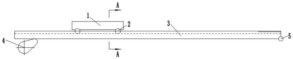
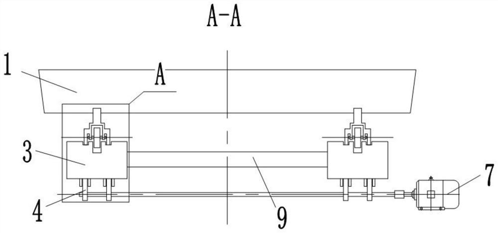
[0037] The present invention is a conveying device for injection molded parts of automobiles, which comprises a conveying car, two rows of casters 2 are arranged under the conveying car 1, two rows of guide rails 3 are arranged under the casters as bearing bodies, and a cam 4 is arranged under one end of the guide rails. The keyway of the output shaft of the motor is matched. The motor is a servo motor. The cam raises the guide rail to a certain inclination angle, and the component force of gravity along the guide rail is used to move down the guide rail. After the transfer vehicle advances to a station on the production line, the servo motor reverses and the guide rail falls to a flat state. At this moment, the worker can continue to process the products on the station. A hinge 5 is provided at the end of the guide rail, and the hinge 5 is hinged with the hinge bracket. The guide rail is provided with accommodating groove 6 for the caster to be embedded in, and the two ends ...

Embodiment 2

[0039]The difference from Embodiment 1 is that instead of the cam, the wedge block 15 is arranged below one end of the guide rail, and the contact position between the guide rail and the wedge block is a smooth transition angle. It is connected with the piston rod of the cylinder; the end of the same side of the guide rail and the hinge is provided with an arc surface 11 with an upward opening; shaft connection.

Embodiment 3

[0041] The difference from Embodiment 1 is that: the two sides of the transport vehicle are provided with deceleration rods 12, and the end of the guide rail is provided with a buffer rod 13 used in conjunction with the deceleration rod, and the buffer rod can rotate around a torsion spring 14.


PUM


Abstract

According to the technical scheme, the automobile injection molding part conveying device comprises a bearing body, at least the two ends of the bearing body are provided with a lifting mechanism and/or a hinge piece respectively, the hinge piece is hinged to a hinge support, and the lifting mechanism drives the bearing body to rotate by a certain angle around the hinge support and is in an inclined state. The conveyed object is conveyed on the bearing body through the gravity of the conveyed object, and when conveying is completed, only the bearing body needs to be adjusted to be horizontally arranged, and the conveyed object loses power and does not move forwards any more. The whole structure is simple, and the conveyed object does not need to be driven to run. The hinging position of the device can be changed through the clutch, so that the bearing body slides bidirectionally. Sliding between the friction blocks and the guide rail is adopted to replace rolling of the trundles on the guide rail, the falling speed of the conveying vehicle on the guide rail can be effectively reduced, and risks caused by inertia can be effectively avoided after the guide rail is turned from an inclined position to a horizontal position.

Description

technical field [0001] The invention relates to the field of production line transmission, in particular to a transmission device that utilizes gravitational potential energy to transmit products on a production line. Background technique [0002] After the injection molding of the automobile bumper, it needs to undergo different follow-up processing at a series of stations before it can be packaged as a finished product. After processing at each station, the bumper needs to be transferred to the next station. Because the bumper of irregular shape is not easy to fix, and the volume is too large, this has just resulted in the inconvenience of utilizing conventional conveyer belts for transmission. [0003] The original way is to place the bumper on the bumper profiling support on the transfer trolley, and adopt the transfer trolleys arranged in sequence to transmit the bumper. After the worker completes the operation at his station, he needs to manually push the trolley to t...

Claims


Application Information

Patent Timeline
Patent Type & Authority Applications(China)
IPC IPC(8): B29C45/17B65G35/00B29L31/30
CPCB29C45/1769B65G35/00B29L2031/3044
Inventor 陈立奎林科徐俊封晓平黄一
Owner 江阴名鸿车顶系统有限公司
Why Eureka
Try Eureka