
A design method of external power supply module for test model against high emission overload

A technology of external power supply and test model, which is applied in the direction of offensive equipment, weapon testing, geometric CAD, etc., can solve the problems of increasing the capacity and volume of the energy storage module, the length of the flight time, and the complexity of the launch preparation process, so as to increase the payload ratio, high economy, and the effect of ensuring launch safety

Active Publication Date: 2022-05-24
中国空气动力研究与发展中心超高速空气动力研究所
View PDF7 Cites 0 Cited by
  • Summary
  • Abstract
  • Description
  • Claims
  • Application Information

AI Technical Summary

Problems solved by technology

Since the flight time of the shells or test models of air cannons, artillery, and electromagnetic guns is short (generally less than 1s), the power supply time of the energy storage module or power supply module can generally meet the power supply requirements of the shells or test models from launch to flight; However, if the launch preparation process is complicated and the preparation time exceeds 1 hour, it is necessary to increase the capacity and volume of the energy storage module or the energy supply module, and an excessively large built-in energy supply module will affect the distribution of the center of mass of the projectile or the test model, and flight stability performance, anti-overload performance, and structural safety, so it is necessary to explore ways to improve external power supply in long-term closed environments to meet long-term energy supply needs
[0004] The external energy supply scheme using direct leads has high requirements on the position of the energy supply contacts. In some closed environments and launch mechanisms, the lead wires and take-up wires of direct leads will affect the structural strength and aerodynamics of shells or test models. The shape and the safety of the test equipment have an impact

Method used

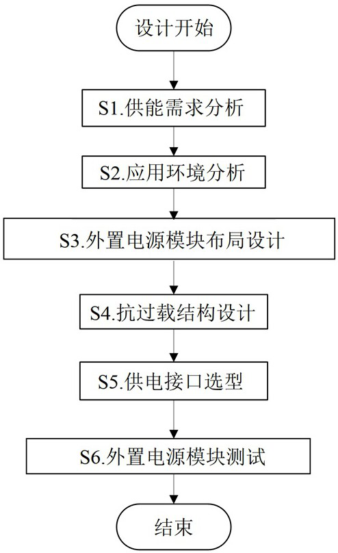
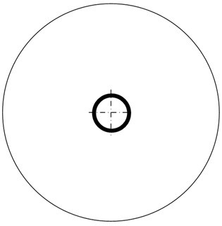
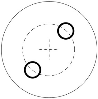

Image

  • A design method of external power supply module for test model against high emission overload
  • A design method of external power supply module for test model against high emission overload
  • A design method of external power supply module for test model against high emission overload

Examples


Embodiment 1

[0106] The application scenario of this embodiment is the launch environment of a secondary light gas gun, and a test model with aerodynamic parameter measurement function is launched. The built-in electrical components of this test model can realize 4-channel parameter measurement, independent power supply for more than 10 seconds, and data logging. From the time the test model enters the closed launch environment, the test preparation time is 4-5 hours. In order to fill the continuous power supply demand of the test model in the test preparation stage, and maintain the built-in power supply capacity and the distribution of the center of mass of the test model, an external power supply that can be thrown as a whole is designed according to the design method of the external power supply module of the test model with resistance to high emission overload of the present invention. .

[0107] First, according to the energy supply demand analysis in step S1, the obtained energy su...


PUM


Abstract

The invention belongs to the technical field of artillery launch, and discloses a design method for an external power supply module of a test model resistant to high launch overload. The external power module design method includes energy supply demand analysis, application environment analysis, external power module layout design, anti-overload structure design, power supply interface selection and external power module testing. The design method of the external power supply module can guide the design of external power supply modules that can be applied to air cannons, artillery, electromagnetic guns and other closed launch conditions to provide long-term power supply for shells with direct measurement functions or test models, and can provide different applications. The design scheme of the occasion can meet the external power supply requirements of large capacity, high overload resistance, no damage to the center of mass of the shell or test model and flight stability, which is conducive to improving the payload ratio of the shell or test model, ensuring launch safety, and has a more High economy.

Description

technical field [0001] The invention belongs to the technical field of artillery firing, and in particular relates to a design method for an external power supply module of a test model against high firing overload. Background technique [0002] Launch a projectile or test model with an electrical device with a measurement function, which can measure the ballistic parameters, flight environment parameters, motion state and other parameters of the projectile or test model in high overload environment (instantaneous overload 1000g~50000g) in real time. Compared with non-contact Measurement, the parameters obtained by direct measurement are more reliable, the description of physical phenomena is closer to the real situation of flight trajectory, and it can realize continuous measurement of the whole process, breaking through the limitations of fixed position and limited field of view of optical non-contact measurement equipment . [0003] In order to realize the direct measure...

Claims


Application Information

Patent Timeline
Patent Type & Authority Patents(China)
IPC IPC(8): G06F30/17F41A31/00
CPCG06F30/17F41A31/00
Inventor 李晶文雪忠陈鲲龙耀柯发伟姜林黄洁
Owner 中国空气动力研究与发展中心超高速空气动力研究所
Learn More