
Slit-lamp microscope, ophthalmic information processing device, ophthalmic system, slit-lamp microscope control method, program, and recording medium

A slit-lamp microscope and slit-light technology, applied in the direction of ophthalmoscope, gonioscope, etc., can solve the problem of no depth direction, unable to provide turbidity distribution, image quality management hindering automatic image analysis and suitable for clear images.

Pending Publication Date: 2022-04-15
KK TOPCON
View PDF4 Cites 0 Cited by
  • Summary
  • Abstract
  • Description
  • Claims
  • Application Information

AI Technical Summary

Problems solved by technology

[0006] First, there is a problem that since the reflected light from the retina is used, it is difficult to manage the brightness of the illuminated image, and it is also difficult to manage (control, adjust) the image quality, so it is not suitable for quantitative diagnosis
Therefore, the diagnosis using the penetrating method largely depends on the subjectivity of the image reader, for example, the grade of cataract cannot be evaluated objectively.
In addition, although automatic image analysis using analysis programs and machine learning has developed rapidly in recent years, the difficulty of image quality management is one of the factors that prevent automatic image analysis from being applied to through-illuminated images
[0007] Second, the problem is that the through-illumination image is a planar image (projection image, projective image) with the fundus as the secondary light source, and there is no information in the depth direction (depth direction, Z direction), so it is impossible to grasp the three-dimensional turbidity distribution
That is to say, the illuminated image can only provide the turbidity distribution on the XY plane orthogonal to the Z direction, but not the turbidity distribution in the Z direction

Method used


Image

  • Slit-lamp microscope, ophthalmic information processing device, ophthalmic system, slit-lamp microscope control method, program, and recording medium
  • Slit-lamp microscope, ophthalmic information processing device, ophthalmic system, slit-lamp microscope control method, program, and recording medium
  • Slit-lamp microscope, ophthalmic information processing device, ophthalmic system, slit-lamp microscope control method, program, and recording medium

Examples


Embodiment Construction

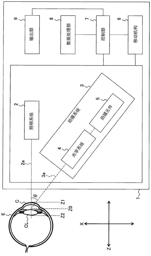
[0090] Hereinafter, some exemplary embodiments will be described in detail with reference to the accompanying drawings. In addition, arbitrary known techniques such as matters disclosed in documents cited in this specification can be combined into the exemplary embodiments.

[0091] A slit lamp microscope according to an exemplary embodiment may be of a fixed installation type or a transportable type. The slit lamp microscope according to the exemplary embodiment has an (automatic) scanning function of acquiring a plurality of cross-sectional images by scanning the anterior eye with slit light, and typically, it can be obtained by an expert (skilled) holder regarding the device. or) not to be used in adjacent conditions or environments. In addition, the slit lamp microscope according to the exemplary embodiment can be used in a situation or an environment where a skilled person is not present, and can also be used in a situation or an environment where a skilled person can re...


PUM


Abstract

A slit-lamp microscope according to an exemplary embodiment includes a scanning unit and a data processing unit. The scanning unit collects a plurality of cross-sectional images by scanning an anterior eye portion of an eye to be examined with slit light. The data processing unit generates opacification distribution information indicating the distribution of opacification portions of the lens of the eye to be examined on the basis of the plurality of cross-sectional images collected by the scanning unit.

Description

technical field [0001] The invention relates to a slit lamp microscope, an ophthalmic information processing device, an ophthalmic system, a control method, a program and a recording medium of the slit lamp microscope. Background technique [0002] In the field of ophthalmology, image diagnosis plays an important role. In image diagnosis, various ophthalmic imaging devices are used. Types of ophthalmic imaging devices include a slit lamp microscope, a fundus camera, a scanning laser ophthalmoscope (SLO), an optical coherence tomography (OCT), and the like. [0003] One of the most widely and frequently used of such various ophthalmic devices is the slit lamp microscope. The slit lamp microscope is used to illuminate the subject's eye with slit light, and observe or photograph the illuminated cross-section with a microscope from oblique or sideways (for example, refer to Patent Documents 1 to 3). [0004] One of the main uses of the slit lamp microscope is to observe the a...

Claims


Application Information

Patent Timeline
Patent Type & Authority Applications(China)
IPC IPC(8): A61B3/135
CPCA61B3/135A61B3/1176A61B3/14A61B3/0025A61B3/10G06T7/11A61B3/0058G06T7/0016G06T2207/10024G06T2207/10028G06T2207/10056G06T2207/30041
Inventor 乔纳森·刘清水仁塚田央
Owner KK TOPCON
Learn More