
Pipeline defect ultrasonic detection device

A detection device, ultrasonic technology, applied in measuring devices, using sound waves/ultrasonic waves/infrasonic waves to analyze solids, using sound waves/ultrasonic waves/infrasonic waves for material analysis, etc., can solve problems such as cracks, difficult realization, and difficult detection of pipeline defects , to improve the accuracy of the

Active Publication Date: 2022-04-15
湖北闪复管道科技有限公司
View PDF6 Cites 0 Cited by
  • Summary
  • Abstract
  • Description
  • Claims
  • Application Information

AI Technical Summary

Problems solved by technology

[0002] During the long-term use of the pipeline, defects such as cracks may occur, which need to be inspected for maintenance. It is difficult to find defects inside the pipeline. Ultrasonic testing is an effective method. When testing, it is necessary to avoid external The interference of sound waves, so as not to affect the accuracy of detection, and the surface of the pipe is curved, the detection head cannot be completely attached to the pipe, and the detection head needs to be perpendicular to the pipe to ensure the accuracy of detection. It is difficult to hold the detection head However, the existing pipeline defect ultrasonic detection device cannot solve the above problems, and the detection accuracy can be further improved. For this reason, the present invention proposes a pipeline defect ultrasonic detection device

Method used


Image

  • Pipeline defect ultrasonic detection device
  • Pipeline defect ultrasonic detection device
  • Pipeline defect ultrasonic detection device

Examples


Embodiment approach

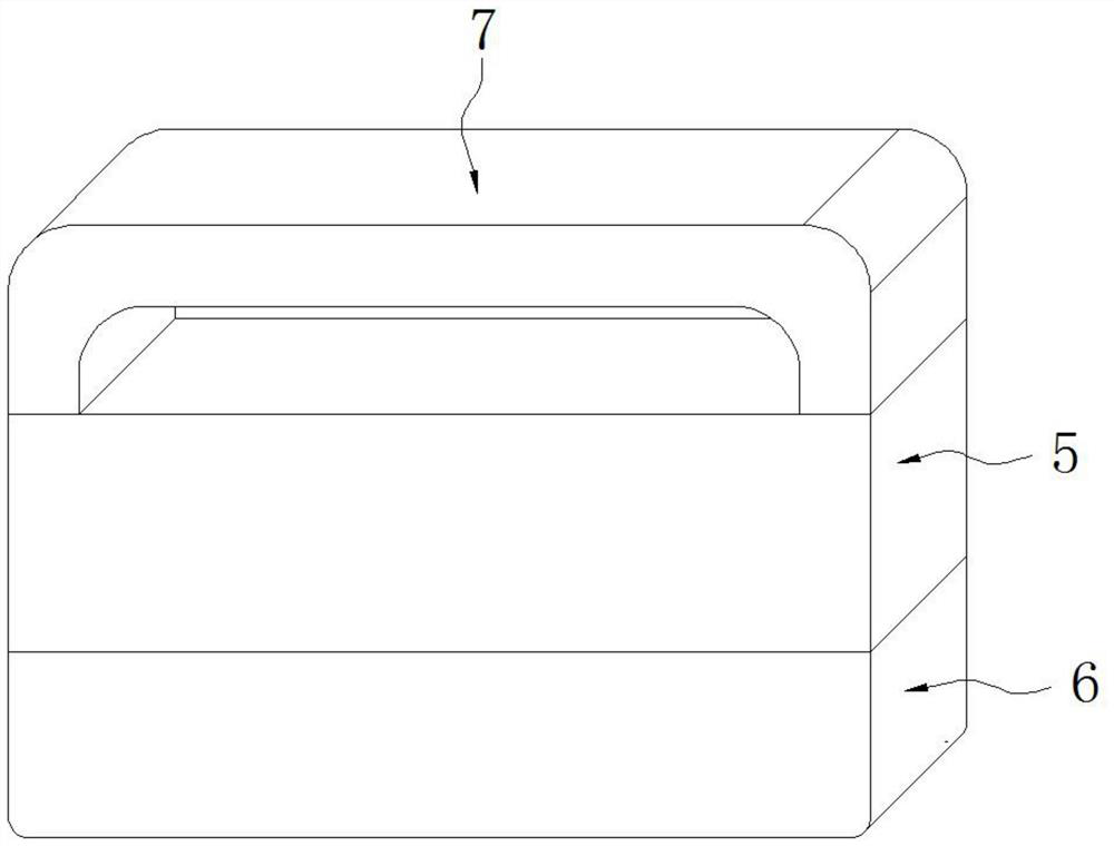
[0021] As a preferred embodiment of the present invention, a handle 7 is fixedly installed on the top of the mounting base 5 .

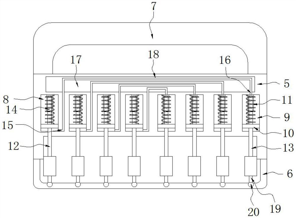
[0022] As a preferred embodiment of the present invention, the spring 11 is sheathed on the telescopic rod 14 , and the spring 11 and the telescopic rod 14 are fixedly connected with the movable seat 10 .

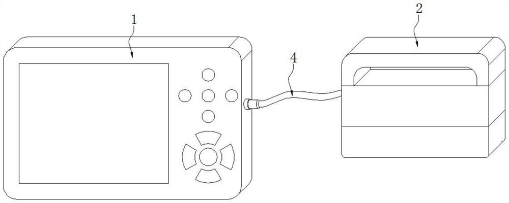
[0023] As a preferred embodiment of the present invention, a transmission line 4 is connected to the main body 1 of the ultrasonic testing device, and the main body 1 of the ultrasonic testing device is connected to the detection head 3 through the transmission line 4 .

[0024] As a preferred embodiment of the present invention, the detection head 3 is fixedly embedded in the bottom of the mounting base 5 .

[0025] As a preferred embodiment of the present invention, the top of the convex ejection groove 9 is filled with hydraulic oil.

[0026] As a preferred embodiment of the present invention, when in use, hold the handle 7 and forcefully atta...


PUM


Abstract

A pipeline defect ultrasonic detection device provided by the present invention comprises an ultrasonic detection device main body, an auxiliary detection device and a detection head, the auxiliary detection device comprises a mounting seat and a rubber sheath, and the rubber sheath is fixedly mounted at the bottom of the mounting seat. The pipeline defect ultrasonic detection device is reasonable in design, a plurality of left convex linkage rods and a plurality of right convex linkage rods are mounted at the bottom of the mounting seat of the auxiliary detection device, the left convex linkage rods and the right convex linkage rods are connected with the left convex linkage rods and the right convex linkage rods, and the left convex linkage rods and the right convex linkage rods are connected with the left convex linkage rods and the right convex linkage rods through the left convex linkage rods and the right convex linkage rods. During detection, in the process that the auxiliary detection device is attached to the surface of a pipeline, the left convex linkage rods and the right convex linkage rods can be attached to the surface of the pipeline in a self-adaptive mode, and the rubber leather sheath is stretched and shaped at the same time, so that the detected position and the detection head are completely isolated from the outside, external sound waves are prevented from influencing detection, and the detection accuracy is improved.

Description

technical field [0001] The invention belongs to the technical field of pipeline detection equipment production, in particular to an ultrasonic detection device for pipeline defects. Background technique [0002] During the long-term use of the pipeline, defects such as cracks may occur, which need to be inspected for maintenance. It is difficult to find defects inside the pipeline. Ultrasonic testing is an effective method. When testing, it is necessary to avoid external The interference of sound waves, so as not to affect the accuracy of detection, and the surface of the pipe is curved, the detection head cannot be completely attached to the pipe, and the detection head needs to be perpendicular to the pipe to ensure the accuracy of detection. It is difficult to hold the detection head However, the existing ultrasonic detection device for pipeline defects cannot solve the above problems, and the detection accuracy can be further improved. Therefore, the present invention pr...

Claims


Application Information

Patent Timeline
Patent Type & Authority Applications(China)
IPC IPC(8): G01N29/04G01N29/22
Inventor 田茂赵训宏平巍汪洋胡俊何战郭永丽
Owner 湖北闪复管道科技有限公司
Learn More