Solidified soil stirring field and solidified soil backfill construction method in narrow high backfill area

A construction method and technology for solidifying soil, applied in the directions of chemical instruments and methods, excavation, fertilization devices, etc., can solve the problems of inability to perform construction by personnel and machinery, high backfilling depth, and narrow backfilling area, so as to achieve reasonable distribution and reuse. , the effect of short curing time

Pending Publication Date: 2022-04-15
CHINA CONSTR EIGHTH ENG DIV
View PDF8 Cites 0 Cited by
  • Summary
  • Abstract
  • Description
  • Claims
  • Application Information

AI Technical Summary

Problems solved by technology

[0004] In order to solve the above technical problems, the present invention provides a solidified soil mixing field and a construction method and construction method of solidified soil backfilling in a narrow high backfill area. Form solidified soil into a fluid state, and backfill the solidified soil into a narrow and high backfill area, which saves a lot of transportation costs and protects the ecological environment. At the same time, it solves the problems of narrow backfill area, high backfill depth, and the inability of personnel and machinery to construct during backfill construction. , and the solidified soil also has a waterproof effect after consolidation, which solves the hidden danger of external wall leakage. At the same time, the solidified soil has a relatively high strength and does not need to be compacted, which saves the tamping process, improves construction efficiency, and reduces construction costs. cost

Method used


Image

  • Solidified soil stirring field and solidified soil backfill construction method in narrow high backfill area
  • Solidified soil stirring field and solidified soil backfill construction method in narrow high backfill area

Examples


Embodiment 1

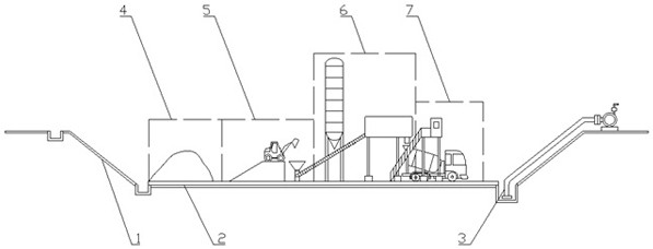
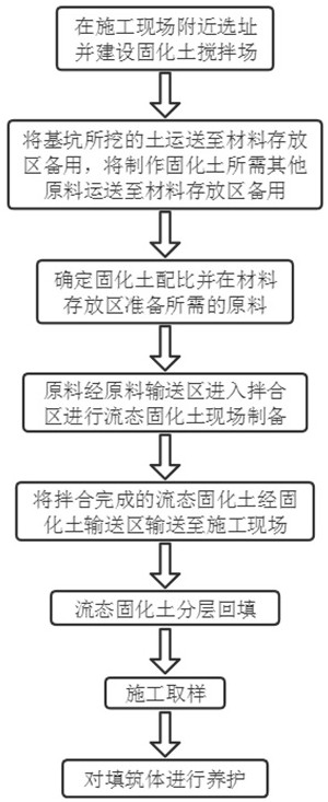
[0058] This embodiment discloses a solidified soil mixing field and the positioning of the solidified soil backfill construction method in the narrow high backfill area, such as figure 1 As shown, it includes a solidified soil mixing field, which is characterized in that it is arranged on a flat place near the construction site, surrounded by slopes 1 that have been treated with grading, and a concrete hardened layer 2 that is high in the middle and low in the surroundings on the bottom surface. Drainage system 3, material storage area 4, raw material delivery area 5, mixing area 6 and solidified soil delivery area 7 are set in the mixing field.

[0059] The hardened concrete layer 2 is processed by C20 concrete, and the hardened concrete layer 2 has a thickness of 10cm-20cm.

[0060] Drainage system 3 comprises drainage ditches, sump well and the water pump that water is drawn out from the sump well.

[0061] A construction method for backfilling solidified soil in a narrow ...


PUM

PropertyMeasurementUnit
thicknessaaaaaaaaaa
strengthaaaaaaaaaa
slumpaaaaaaaaaa

Abstract

The invention relates to a stabilized soil mixing plant and a stabilized soil backfill construction method in a narrow high backfill area, the stabilized soil mixing plant is arranged at a flat position near a construction plant, a slope subjected to slope making treatment is arranged on the periphery of the stabilized soil mixing plant, and a concrete hardened layer with a high middle and a low periphery and a drainage system are arranged on the bottom surface of the stabilized soil mixing plant; a material storage area, a raw material conveying area, a mixing area and a solidified soil conveying area are arranged in the stirring field, soil excavated from a foundation pit is processed on site in the solidified soil stirring field to be prepared into flow-state solidified soil, the flow-state solidified soil is backfilled into a narrow high backfilling area, a large amount of transfer cost is saved, the ecological environment is protected, and the construction efficiency is improved. The problems that in backfilling construction, the backfilling area is narrow, the backfilling depth is high, and personnel and machinery cannot conduct construction are solved, the solidified soil has a waterproof effect after being solidified, the hidden danger of leakage of the outer wall is solved, meanwhile, the solidified soil has quite high strength and does not need to be compacted, the tamping procedure is omitted, the construction efficiency is improved, and the construction cost is reduced.

Description

technical field [0001] The invention relates to the technical field of building construction, in particular to a solidified soil backfill construction method for a solidified soil mixing field and a narrow high backfill area. Background technique [0002] With the rapid development of the construction industry, in order to solve the problem of tight urban land use, underground space construction projects are becoming more and more extensive. For underground projects such as basements and underground shopping malls, there is a large amount of earthwork excavation, which often requires high costs. Transshipment treatment, even dumping on the ground, increases the construction cost and causes damage to the ecological environment at the same time. [0003] At the same time, after the construction of the main body, it is necessary to backfill the outer walls of the basement, underground shopping malls, etc. The traditional technology mostly uses plain soil or lime soil layered wi...

Claims


Application Information

Patent Timeline
Patent Type & Authority Applications(China)
IPC IPC(8): E02D17/12E02D17/00E02D3/12C09K17/00
Inventor 王鹏任耿高振朋汪雷雷谢佳桓
Owner CHINA CONSTR EIGHTH ENG DIV
Why Eureka
Try Eureka