Paver with novel mechanism and paving process
A paver, a new type of technology, applied in the direction of roads, road repair, roads, etc., can solve the problems of the limited turning angle of the walking device, unrealizable, small turning radius, etc., to ensure the transportation height of the whole machine and ensure the paving. quality effect
- Summary
- Abstract
- Description
- Claims
- Application Information
AI Technical Summary
Problems solved by technology
Method used
Image
Examples
Embodiment 1
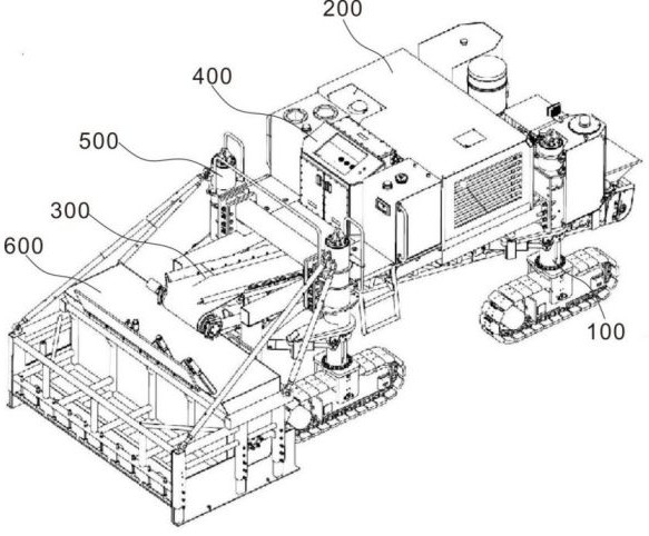
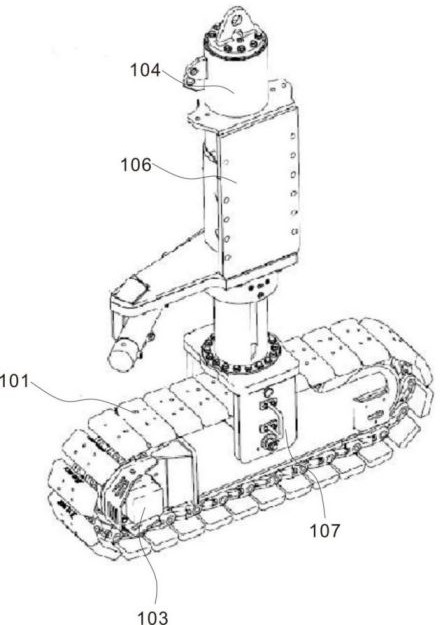
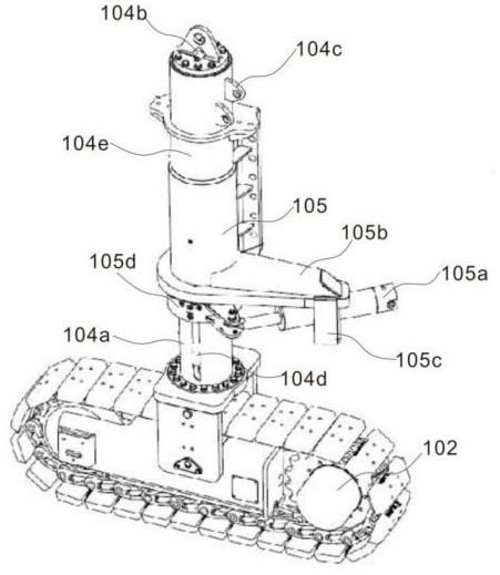
[0064] Example 1: Please refer to Figure 1-3 , the present invention provides a paver with a new type of mechanism, including a running device 100, including a crawler belt assembly 101, a reducer 102, a driving motor 103, a lifting leg 104, a steering device, a body connecting plate and a lifting hydraulic cylinder Support; the drive motor 103 shaft is connected to the reducer 102 to drive the crawler assembly 101 to rotate; the crawler assembly 101, the reducer 102 and the drive motor 103 are installed under the steering device; the lifting leg 104 passes through the lifting hydraulic cylinder support 107 is connected to the crawler belt; the walking device 100 is connected to the whole body through the body connecting plate 106; the power device 200 provides power for the movement of the entire paver; the conveying device 300 is used to transport materials; the attitude perception and control system 400 and The hydraulic system 500 can be fed back to the hydraulic system 5...
Embodiment 2
[0068] Example 2: Please refer to Figure 5-7 , the rear mold 600 includes a mold frame 601, left and right side plates 602, side plate adjustment hydraulic cylinder 603, feed bin 604, feed baffle 605, dense vibrating rod 606, material distribution vibrating rod 607, forming mold 608, Rear mold connecting rod 609, side plate sliding structure 610, feed bin fixed shaft 611, rear mold connecting flange 612 and front side plate 613, left and right side plates 602 are connected with mold frame 601 through side plate sliding structure 610, and at the same time The lower end of the piston rod of the side plate adjustment hydraulic cylinder 603 is hinged, and the conveyor belt motor 305 drives the conveyor belt 304 to rotate through the conveyor belt drive roller 306 connected to its rotating shaft, so that the conveyor device 300 can work; the left and right side plates 602 adjust the hydraulic pressure through the side plates. The expansion and contraction of the cylinder 603 and t...
Embodiment 3
[0072] Example 3: Please refer to Figure 8 and Figure 9 The compact vibrating rod 606 includes a rod body 606a, the end of the rod body 606a is movably inserted into the curved guide tube 606b, and the upper port of the curved guide tube 606b is provided with a shock absorbing bracket 606c sleeved on the surface of the rod body 606a, The setting of the shock absorber 606c facilitates reducing the impact of the rod body 606a on the overall vibration of the device during the working process. The outer surface of the shock absorber 606c is equidistant from the circumference and is provided with a buffer spring 606d connected to the inner wall of the curved guide cylinder 606b;
[0073] A sealed chamber 606g is provided in the curved guide cylinder 606b, a sliding block 606f movable in the sealed chamber 606g is provided at the bottom end of the rod body 606a, and an air injection joint 606e communicating with the sealed chamber 606g is provided on the surface of the curved guid...
PUM
 Abstract
Description
Claims
Application Information
 - R&D Engineer
- R&D Manager
- IP Professional
- Industry Leading Data Capabilities
- Powerful AI technology
- Patent DNA Extraction
Browse by: Latest US Patents, China's latest patents, Technical Efficacy Thesaurus, Application Domain, Technology Topic, Popular Technical Reports.
© 2024 PatSnap. All rights reserved.Legal|Privacy policy|Modern Slavery Act Transparency Statement|Sitemap|About US| Contact US: help@patsnap.com


