Auxiliary equipment for winding steel wire rope

An auxiliary equipment, steel wire rope technology, applied in the direction of conveying filamentous materials, thin material processing, transportation and packaging, etc., can solve the problem of affecting the uniformity of winding, the difficulty of stable control of the feeding direction and feeding state of the wire rope, and the connection of winding discs Insufficient stability and other problems, to achieve the effect of not easy to shift, uniform winding, high motion stability

Active Publication Date: 2022-04-15
MAANSHAN FASTEN SCI & TECH CO LTD
View PDF9 Cites 2 Cited by
  • Summary
  • Abstract
  • Description
  • Claims
  • Application Information

AI Technical Summary

Problems solved by technology

[0003] like figure 1 The prior art scheme of a wire rope winding device shown is to wind the wire rope by clamping and fixing the winding disk laterally, and using the drive motor to drive the winding disk to rotate; this winding method has great influence on the connection stability of the winding disk. Insufficient, the position of the winding disk is relatively fixed, so that the steel wire rope is easy to accumulate in some positions on the winding disk, and it is difficult to ensure the uniform distribution of the steel wire rope on the winding disk; at the same time, it is difficult to stably control the feeding direction and feeding state of the steel wire rope, which further affects uniformity of winding

Method used


Image

  • Auxiliary equipment for winding steel wire rope
  • Auxiliary equipment for winding steel wire rope
  • Auxiliary equipment for winding steel wire rope

Examples


Embodiment Construction

[0024] The following will clearly and completely describe the technical solutions in the embodiments of the present invention with reference to the accompanying drawings in the embodiments of the present invention. Obviously, the described embodiments are only some, not all, embodiments of the present invention. Based on the embodiments of the present invention, all other embodiments obtained by persons of ordinary skill in the art without making creative efforts belong to the protection scope of the present invention.

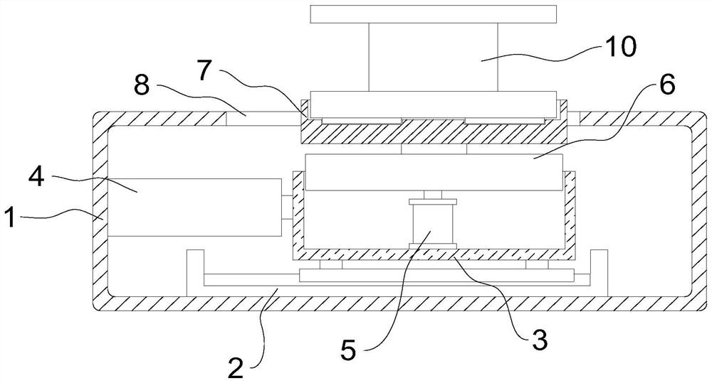
[0025] In the embodiment of the present invention, please refer to Figure 2-Figure 3 , an auxiliary equipment for wire rope winding, comprising a workbench 1, the bottom of the inner wall of the workbench 1 is fixedly connected with a push guide rail 2, the inner wall of the push guide rail 2 is slidably connected with a mounting frame 3, and one side of the inner wall of the workbench 1 is fixedly connected with an adjustment Cylinder 4, the output end of th...


PUM


Abstract

The auxiliary equipment for winding the steel wire rope comprises a workbench, a driving motor is arranged in the workbench, the output end of the driving motor is fixedly connected with a lifting table, a butt joint groove is formed in the top of the lifting table, and a winding disc is connected to the inner wall of the butt joint groove in a clamped mode; an inclined clamping groove is formed in the top of the winding disc, a clamping piece used for clamping the end of a steel wire rope is slidably connected into the clamping groove, and a conveying guide mechanism used for guiding the steel wire rope is fixedly installed on one side of the workbench. When winding operation is carried out, the winding disc is limited and fixed in a vertical posture through the butt joint groove, and the driving motor is used for driving the winding disc to rotate integrally, so that the winding disc is not prone to displacement during winding operation, and the movement stability is higher; and meanwhile, the lifting cylinder is used for driving the winding disc to integrally lift and move during winding operation, so that the steel wire rope is wound on the surface of the winding disc more uniformly.

Description

technical field [0001] The invention relates to the technical field of steel wire rope production, in particular to auxiliary equipment for winding steel wire ropes. Background technique [0002] When the steel wire rope is processed and collected, it needs to be wound on a collection tray, and then shipped as a product. During the winding operation, it is necessary to use auxiliary equipment to improve the efficiency of the winding operation. [0003] Such as figure 1 The prior art scheme of a wire rope winding device shown is to wind the wire rope by clamping and fixing the winding disk laterally, and using the drive motor to drive the winding disk to rotate; this winding method has great influence on the connection stability of the winding disk. Insufficient, the position of the winding disk is relatively fixed, so that the steel wire rope is easy to accumulate in some positions on the winding disk, and it is difficult to ensure the uniform distribution of the steel wir...

Claims


Application Information

Patent Timeline
Patent Type & Authority Applications(China)
IPC IPC(8): B65H54/44B65H54/28B65H57/12B65H63/00B65H57/04B65H59/36
CPCB65H54/44B65H54/2803B65H57/12B65H63/00B65H57/04B65H59/36B65H2701/35
Inventor 周立君魏志远
Owner MAANSHAN FASTEN SCI & TECH CO LTD
Why Eureka
Try Eureka