
Length-controllable breathing machine threaded pipe and threaded pipe length auxiliary control device

An auxiliary control device and threaded tube technology, applied in the direction of respirators, etc., can solve the problems of increasing the path length and influence of ventilation, and achieve the effect of reducing invalid ventilation paths, avoiding influence, and precise adjustment

Inactive Publication Date: 2022-04-15
FOURTH HOSPITAL OF HEBEI MEDICAL UNIV
View PDF0 Cites 0 Cited by
  • Summary
  • Abstract
  • Description
  • Claims
  • Application Information

AI Technical Summary

Problems solved by technology

[0003] The existence of the threaded pipe of the ventilator is to make the connecting pipe have proper ductility and prevent the ventilator pipe from falling off due to the movement of the patient. However, the current threaded pipe has disadvantages. The threaded pipe is easy to be stretched directly, and the stretched threaded pipe increases Ineffective ventilation, increasing the path length of ventilation, causing unnecessary impact

Method used


Image

  • Length-controllable breathing machine threaded pipe and threaded pipe length auxiliary control device
  • Length-controllable breathing machine threaded pipe and threaded pipe length auxiliary control device
  • Length-controllable breathing machine threaded pipe and threaded pipe length auxiliary control device

Examples


Embodiment 1

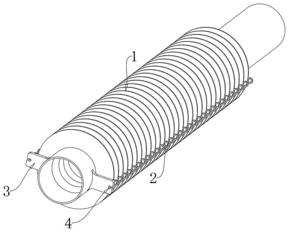
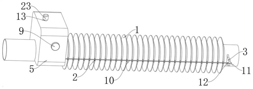
[0035] A ventilator threaded tube with controllable length, comprising a main pipe body 1, collars 2 are fixedly connected to both sides of each nodule of the main pipe body 1, two sets of symmetrical connecting plates 3 are fixedly connected to one end of the main pipe body 1, two sets of The connecting plates 3 are located on the same vertical plane, and the two sets of connecting plates 3 are provided with clamping holes 4 on the side away from the main body 1. The two sets of clamping holes 4 correspond to the respective sets of collars on both sides of the main tube 1. The axes of the two are coincident, and the two sets of connecting plates 3 are provided with slots connecting the clamping holes 4 on the side away from the main body 1 .

[0036] It should be noted that the diameter of the clamping hole 4 is smaller than that of the collar 2, and the clamping hole 4, the collar 2 and the slot are used to facilitate the connection of the auxiliary control device for the len...

Embodiment 2

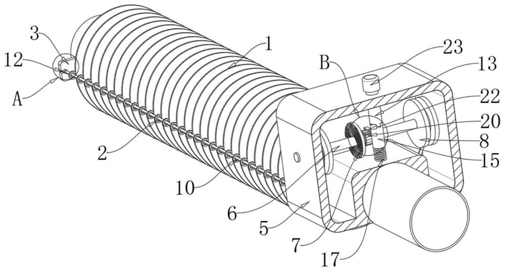
[0038] An auxiliary control device for the length of a threaded pipe, which is used to control the threaded pipe of Embodiment 1, including a casing 5, the casing 5 is fixedly connected to the end of the main pipe body 1 away from the connecting plate 3, and the casing 5 cooperates with the connecting plate 3 to pull the main pipe The body 1 controls the winding mechanism of its length, and the winding mechanism is equipped with a limit mechanism for limiting the length of the main body 1 .

[0039] The winding mechanism includes a rotating rod 6, a coil spring 7 and a winding roller 8. The two ends of the rotating rod 6 are respectively connected to the two sides of the inner wall of the housing 5 and run through the housing 5. The coil spring 7 is wound on the rotating rod 6 and the two ends are respectively Fixedly connected with the rotating rod 6 and the casing 5, two groups of winding rollers 8 are provided, and the two groups of winding rollers 8 are fixedly connected to...

Embodiment 3

[0044]An auxiliary control device for the length of a threaded pipe. On the basis of the second embodiment, the limit mechanism includes a rotating pipe 13 and a block 14. The rotating pipe 13 is arranged perpendicular to the rotating rod 6. The rotating pipe 13 is rotatably connected to the casing 5 and penetrates the casing. 5. There are two sets of clamping blocks 14, and the two sets of clamping blocks 14 are symmetrically and fixedly connected to the bottom of the rotating tube 13, and the side walls of the clamping blocks 14 are arc-shaped.

[0045] Specifically, the limit mechanism includes a resisting tube 15, a rectangular column 16, and an elastic member 17. The top of the resisting tube 15 cooperates with two sets of blocks 14 to have two sets of primary card slots 18 and secondary card slots 19. The two sets of primary card slots The slots 18 and the secondary card slots 19 are distributed in a cross shape, the primary card slot 18 fits with the bottom part of the c...


PUM


Abstract

The invention discloses a length-controllable breathing machine threaded pipe and a threaded pipe length auxiliary control device, and provides the following scheme that the length-controllable breathing machine threaded pipe comprises a main pipe body, lantern rings are fixedly connected to the two sides of each node of the main pipe body, and two sets of symmetrical connecting plates are fixedly connected to one end of the main pipe body; the threaded pipe length auxiliary control device comprises a shell, the shell is fixedly connected to the end, away from the connecting plate, of the main pipe body, the shell and the connecting plate are matched with a winding mechanism used for pulling the main pipe body to control the length of the main pipe body, and the winding mechanism is matched with a limiting mechanism used for limiting the length of the main pipe body. By arranging the winding mechanism and the limiting mechanism, the maximum telescopic length of the threaded pipe is controlled under the condition that the telescopic capacity of the threaded pipe is not affected, and invalid ventilation paths can be effectively reduced; the maximum length of the threaded pipe is controlled through the ruler belt, and the maximum length of the threaded pipe can be accurately adjusted according to the scales of the ruler belt.

Description

technical field [0001] The invention relates to the field of medical devices, in particular to a length-controllable threaded tube of a ventilator and an auxiliary control device for the length of the threaded tube. Background technique [0002] In modern clinical medicine, the ventilator, as an effective means of artificially replacing the spontaneous ventilation function, has been widely used in respiratory failure caused by various reasons, anesthesia respiratory management during major surgery, respiratory support treatment and emergency resuscitation. Occupying a very important position in the field of modern medicine, the ventilator is a vital medical device that can prevent and treat respiratory failure, reduce complications, save and prolong the patient's life. The gas channel between the artificial airway or the mask and other connecting devices ensures that the ventilator sends air into the lungs and the gas is discharged from the lungs. It is generally a threaded ...

Claims


Application Information

Patent Timeline
Patent Type & Authority Applications(China)
IPC IPC(8): A61M16/08
CPCA61M16/08
Inventor 朱桂军霍焱郭春金银银高鹏尹彦玲申康康张坤张涛赵聪聪郭少罕李斌史海雨李波葛胜梅陈玉红韩利南马淑婷
Owner FOURTH HOSPITAL OF HEBEI MEDICAL UNIV
Learn More