Eureka AIR delivers breakthrough ideas for toughest innovation challenges, trusted by R&D personnel around the world.

Method and device for determining switching current threshold value of power factor correction module

A power factor correction and switching current technology, which is applied in the direction of output power conversion device, heating method, electrical components, etc., can solve the problems of low bus voltage of air conditioner, abnormal operation of air conditioner, abnormal operation of PFC, etc., so as to avoid putting into use Effect

Pending Publication Date: 2022-04-12
BEIJING XIAOMI MOBILE SOFTWARE CO LTD
View PDF0 Cites 0 Cited by
  • Summary
  • Abstract
  • Description
  • Claims
  • Application Information

AI Technical Summary

Problems solved by technology

[0003] The air-conditioning system will set the corresponding PFC error-on current threshold and error-off current threshold according to the work requirements. If the two thresholds differ greatly, the bus voltage of the air conditioner will be too low, and the frequency of the air conditioner will not increase, making the air conditioner unable to work normally. The difference between the two thresholds is small, and the PFC will appear in the wrong-on state or wrong-off state, resulting in abnormal operation of the PFC. Therefore, it is necessary to adjust the wrong-on current threshold and the wrong-off current threshold of the PFC.

Method used


Image

  • Method and device for determining switching current threshold value of power factor correction module
  • Method and device for determining switching current threshold value of power factor correction module
  • Method and device for determining switching current threshold value of power factor correction module

Examples


Embodiment Construction

[0054] Reference will now be made in detail to the exemplary embodiments, examples of which are illustrated in the accompanying drawings. When the following description refers to the accompanying drawings, the same numerals in different drawings refer to the same or similar elements unless otherwise indicated. The implementations described in the following exemplary examples do not represent all implementations consistent with the present disclosure. Rather, they are merely examples of apparatuses and methods consistent with aspects of the present disclosure as recited in the appended claims.

[0055] It should be noted that in the present disclosure, the terms "S101", "S102" and the like in the specification, claims and drawings are used to distinguish steps, and it is not necessary to understand that the method steps are performed in a specific order or sequential order.

[0056] Specific embodiments of the present disclosure will be described in detail below in conjunction...


PUM


Abstract

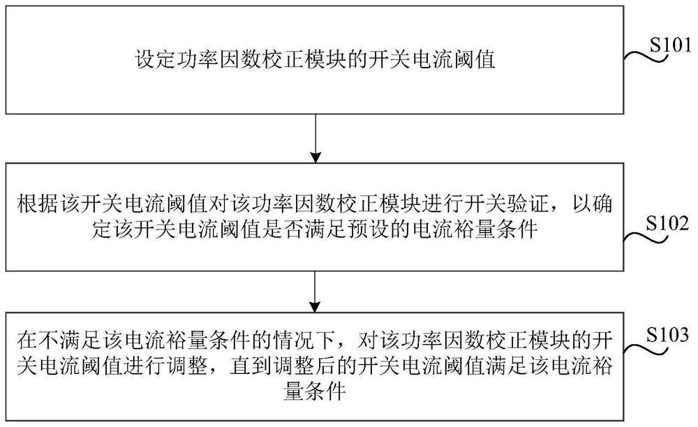
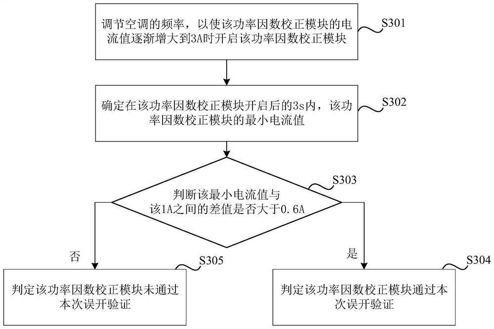
The invention relates to a method and device for determining a switching current threshold value of a power factor correction module, and solves the problem of abnormal control of the power factor correction module caused by mistaken switching on or switching off of the power factor correction module in the prior art. The method comprises the following steps: setting a switching current threshold value of a power factor correction module; performing switching verification on the power factor correction module according to the switching current threshold value to determine whether the switching current threshold value meets a preset current margin condition or not; and when the current margin condition is not met, adjusting the switching current threshold value of the power factor correction module until the adjusted switching current threshold value meets the current margin condition. The switching current threshold value of the power factor correction module is adjusted, so that the situation that the bus voltage of the air conditioner is too low and the air conditioner cannot work normally due to the fact that the difference between the mistakenly-turned-on current threshold value and the mistakenly-turned-off current threshold value of the power factor correction module is large is avoided; and the power factor correction module which may be in a mistaken switching-on state or a mistaken switching-off state is prevented from being put into use.

Description

technical field [0001] The present disclosure relates to the technical field of air conditioning control, and in particular to a method and a device for determining a switch current threshold of a power factor correction module. Background technique [0002] The air-conditioning system mainly controls the bus voltage through the power factor correction module (PFC, Power Factor Correction) so that loads such as compressors can operate reliably. Therefore, the reliability of PFC plays an important role in the stable operation of the air-conditioning system. [0003] The air-conditioning system will set the corresponding PFC error-on current threshold and error-off current threshold according to the work requirements. If the two thresholds differ greatly, the bus voltage of the air conditioner will be too low, and the frequency of the air conditioner will not increase, making the air conditioner unable to work normally. If the difference between the two thresholds is small, th...

Claims


Application Information

Patent Timeline
IPC IPC(8): H02M1/42F24F11/88F24F11/89
CPCY02B70/10
Inventor 单联瑜
Owner BEIJING XIAOMI MOBILE SOFTWARE CO LTD
Why Eureka
Eureka Blog
Learn More