Cable erecting and supporting device for mechanical and electrical installation

A support device and installation technology, applied in the direction of cable laying equipment, etc., can solve the problems that the bracket has no telescopic function, the cable is easily damaged, and there is no traction and movement, so as to simplify the preparation work in the early stage, reduce the number of equipment, and facilitate storage and storage Effect

Inactive Publication Date: 2022-04-12
江苏丰辉环保科技有限公司
View PDF0 Cites 2 Cited by
  • Summary
  • Abstract
  • Description
  • Claims
  • Application Information

AI Technical Summary

Problems solved by technology

Cables placed directly on the ground are easy to be damaged, and buried below the ground is not only cumbersome and expensive, so a device is needed to transport the cables to the designated location so that the erector can fix them
[0003] But, there are following problems in the cable erection support device that has come out now: 1. Most of the devices are simple and light in structure, and cannot bear the larger cables of quality; It is not easy to cut the thick and thick cables. During the construction process, the cable needs to be cut manually at the designated position. Most devices lack this function. 4. There is no device for traction and movement, which is not convenient for connecting vehicles to move and human power to push

Method used


Image

  • Cable erecting and supporting device for mechanical and electrical installation
  • Cable erecting and supporting device for mechanical and electrical installation
  • Cable erecting and supporting device for mechanical and electrical installation

Examples


Embodiment Construction

[0031] The following will clearly and completely describe the technical solutions in the embodiments of the present invention with reference to the accompanying drawings in the embodiments of the present invention. Obviously, the described embodiments are only some, not all, embodiments of the present invention. Based on the embodiments of the present invention, all other embodiments obtained by persons of ordinary skill in the art without making creative efforts belong to the protection scope of the present invention.

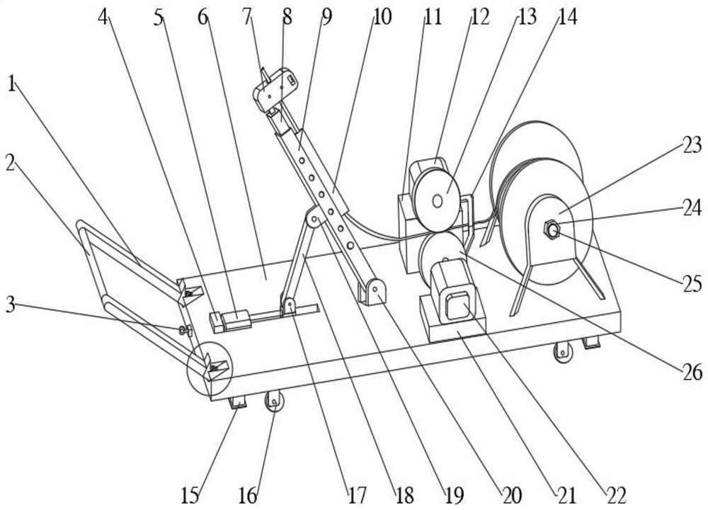
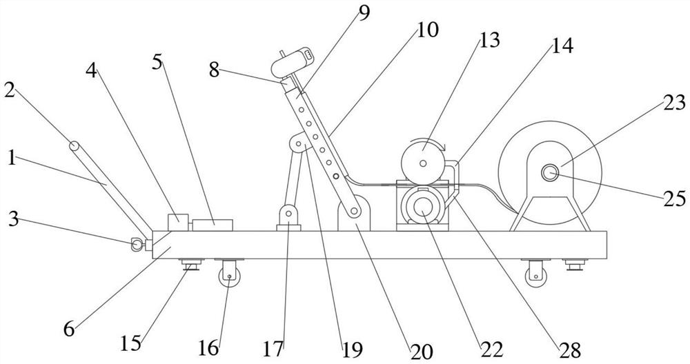
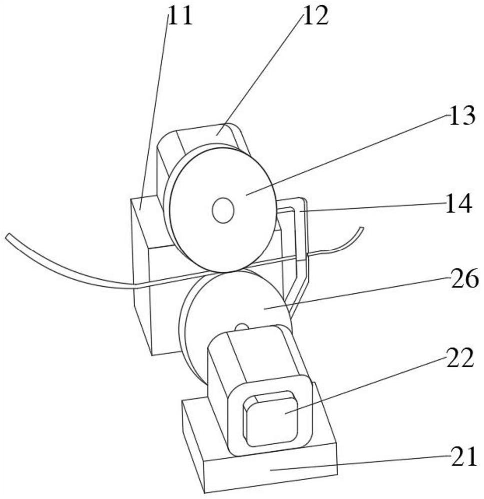
[0032] see Figure 1-10 The present invention provides a technical solution: a cable erection support device for electromechanical installation, including a chassis, a cable unwinding part, a cable pulling part, and a placement part, and the cable laying part, the cable pulling part, and the placement part are all arranged on the chassis, The placement part is located on one side of the cable traction part, and the cable release part is located on the other si...


PUM


Abstract

The invention discloses a cable erection supporting device for electromechanical installation, and belongs to the technical field of cable erection. The cable laying device comprises a chassis, a cable laying part, a cable traction part and a placement part, the cable laying part, the cable traction part and the placement part are all arranged on the chassis, the placement part is located on one side of the cable traction part, the cable laying part is located on one side of the cable traction part, and the chassis supports the cable laying part, the cable traction part and the placement part. The placement component fixes a cable cylinder or winds a certain amount of cables, the cable traction component pulls the cables out of the placement component, the cable traction component can cut off the cables at a designated position, and the cable unwinding component unwinds the cables at the designated position at a certain height to assist cable erection personnel in installation. The cable traction component has a function of automatically cutting off according to the required cable length, and the required cable part can continuously move in the cable laying component to reach a designated position to assist cable erection personnel in installation.

Description

technical field [0001] The invention relates to the technical field of cable erection, in particular to a cable erection support device for electromechanical installation. Background technique [0002] With the popularization of large-scale specialized and automated electromechanical equipment, the electromechanical installation industry has emerged as the times require. Among them, cable erection has become a long-standing problem in this industry due to the huge amount of engineering, high safety requirements, and difficult cable laying. Cables are usually twisted by several or groups of conductors (at least two in each group), each group of conductors is insulated from each other, and is often twisted around a center, and the entire outer surface is covered with a highly insulating covering . Cables placed directly on the ground are easily damaged, and buried below the ground is not only cumbersome and costly, so a device is needed to transport the cables to a designated...

Claims


Application Information

Patent Timeline
Patent Type & Authority Applications(China)
IPC IPC(8): H02G1/06
Inventor 周顶勇
Owner 江苏丰辉环保科技有限公司
Why Eureka
Try Eureka